


Power supplies for computers have improved steadily in power delivery and efficiency over the last couple of decades, but the most significant change was when the cabling became modular and sleeved, improving convenience and aesthetics when installing it in a PC build.
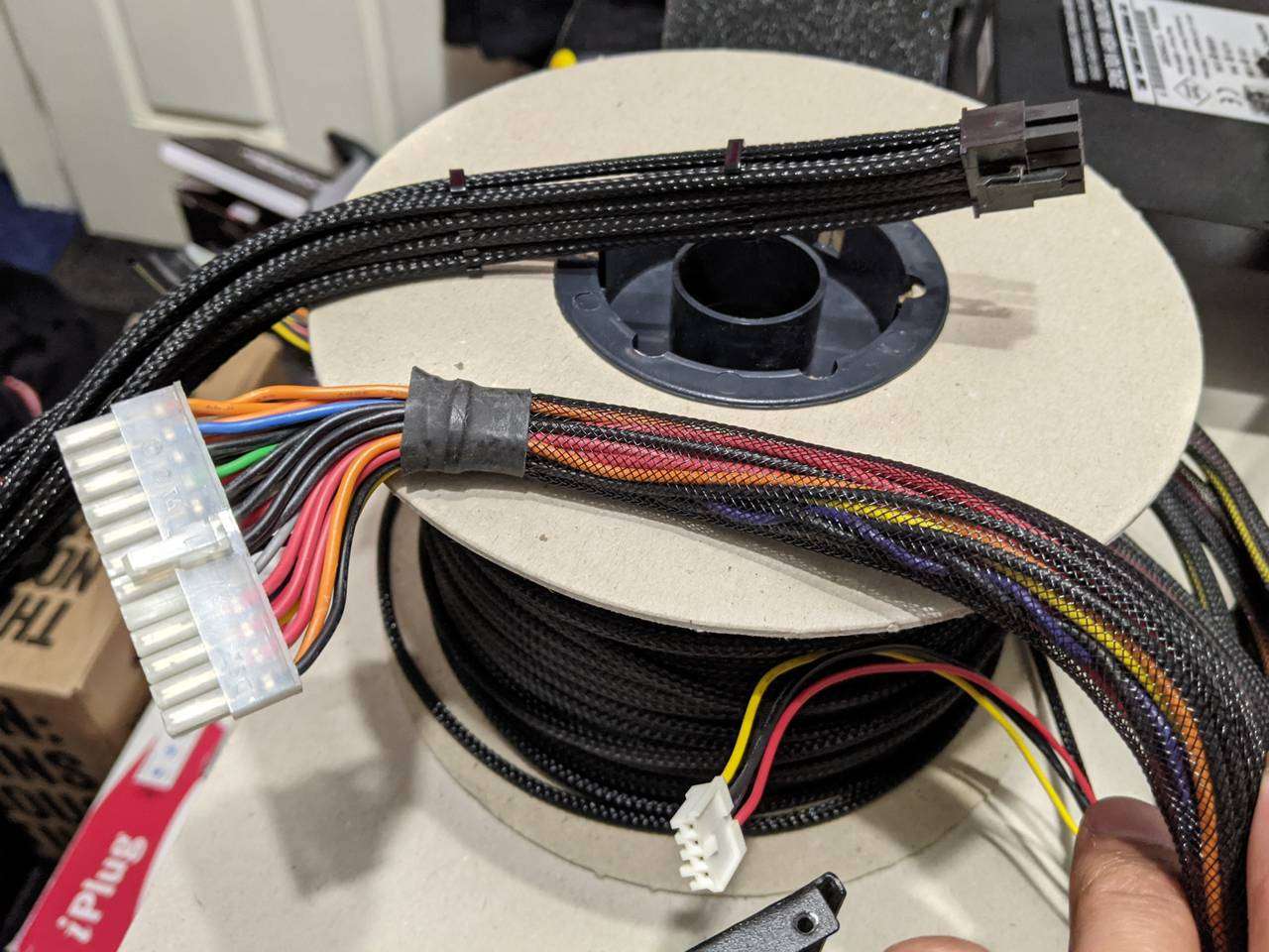
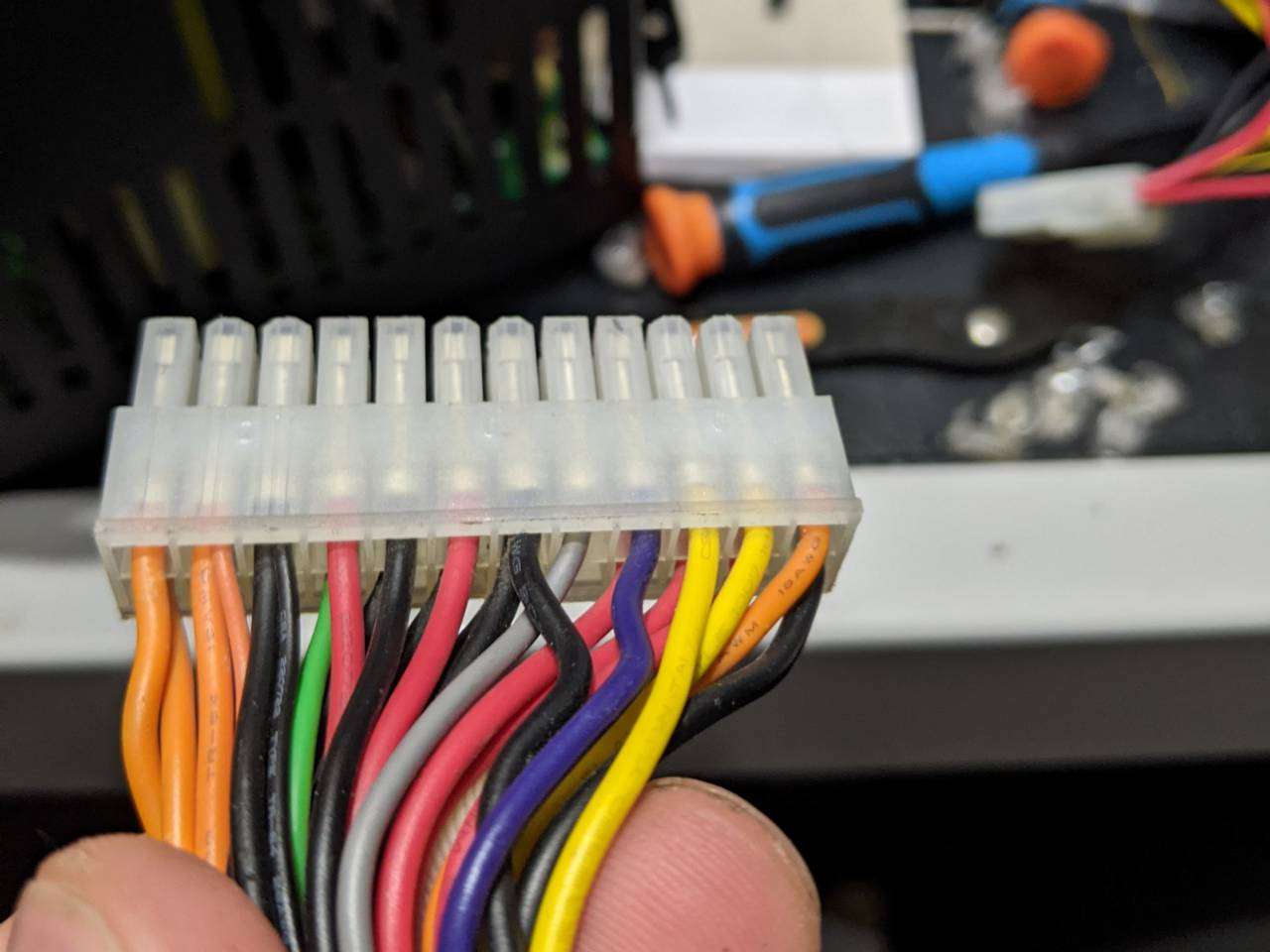
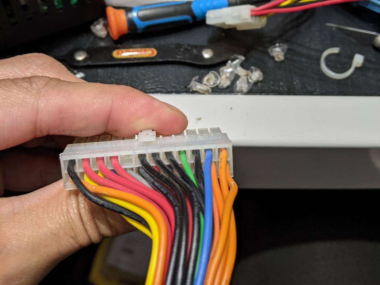
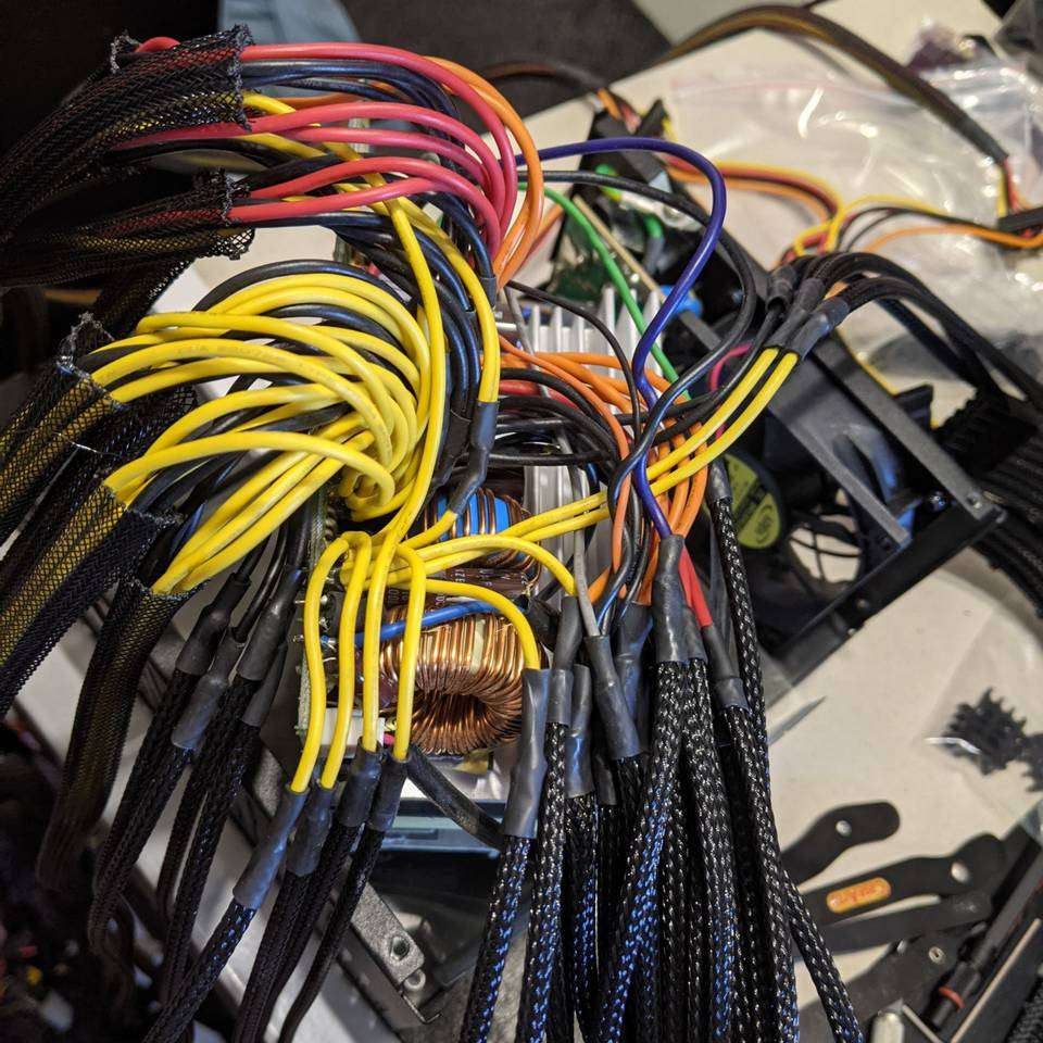
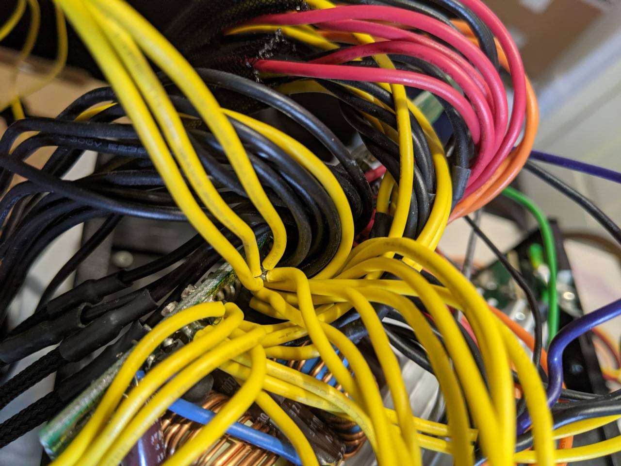
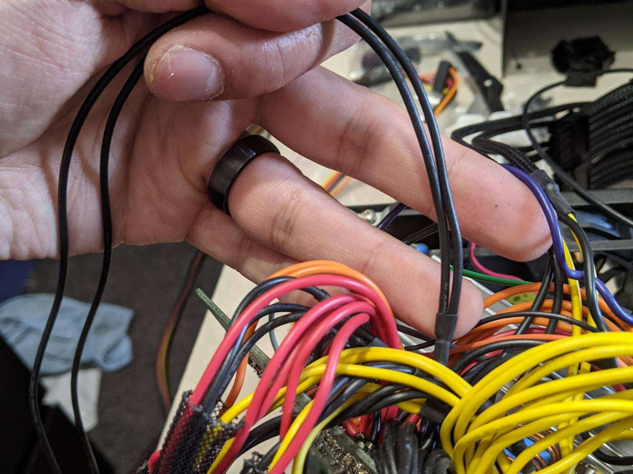
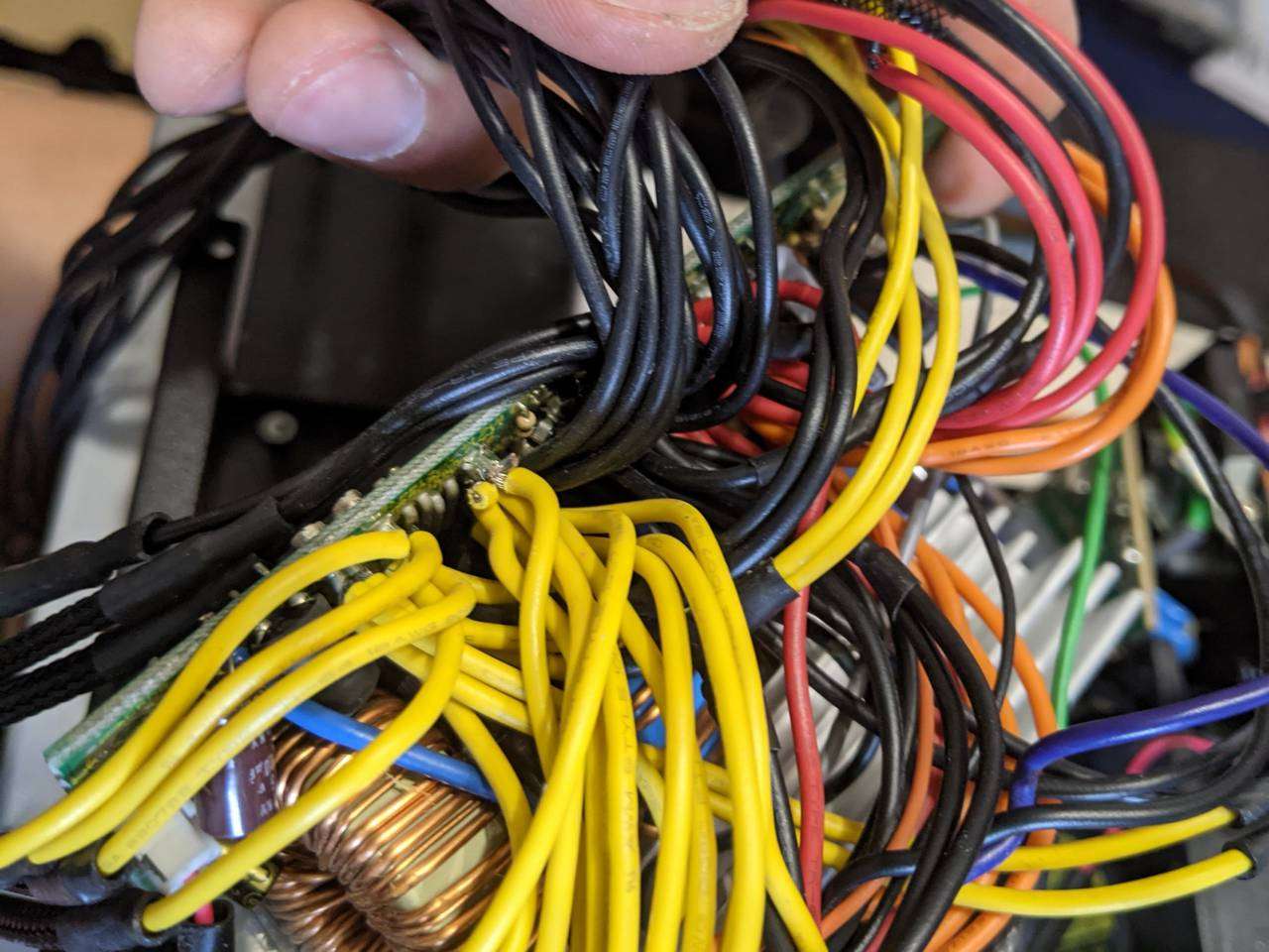
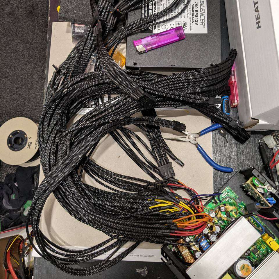
The PC Power & Cooling Silencer 750 Quad SLI PSU was an absolute beast when it was released, offering 60A on a single 12V rail when pretty much everything else was still farting around with multiple weak rails. It’s still a capable to deliver power to a PC with today’s hardware, but is let down by its “first generation” of cable sleeving with the flaws of its day. The sleeving is more like a net, with a very open weave, so you can see the multi-colour wires inside and also along the completely unsleeved sections. The connectors are mostly a translucent white aside from the PCIe 6 pin and 6+2 pin, and SATA power.
By resleeving the cables individually it will look better and be easier to convince into a pleasing and convenient shape when routing the power cables.
MDPC-X sleeving
There are various types of sleeving, provided by a handful of manufacturers/suppliers around the world. I wanted a flexible type of sleeving that can also hold a shape without sagging or flopping about. This ruled out paracord and left the nylon/plastic braided options. I wanted good coverage of the cable beneath and found that MDPC-X sleeving is regarded as amongst the best in the world, and as it is based in Germany, ordering some to me in the UK was reasonable with postage compared to other manufactuers in the US.
I measured out the length of each run of cables from the PSU, to get an idea of the total length of each individual cables. As I planned to sleeve other components like pumps and fans, I opted to get the 100m reel of blackest-black small sleeving, some clear heatshrink, some black heatshrink as well as some black connectors and cable combs.
Heatshrink-less sleeving technique
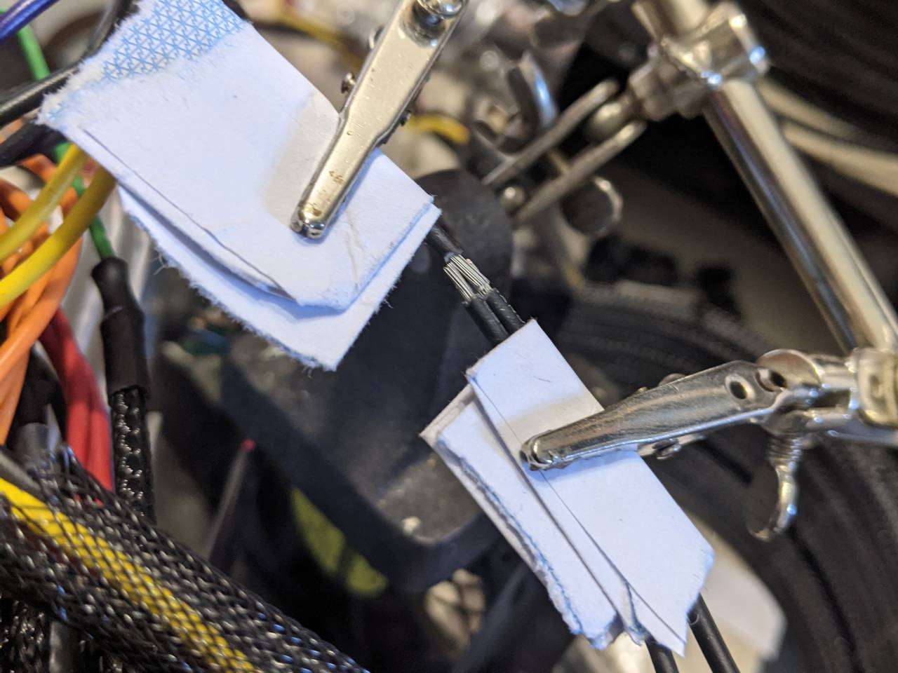
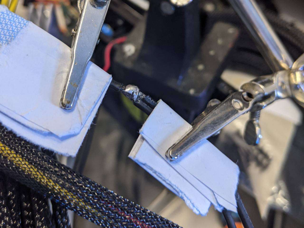
I used the “heatshrink-less” sleeving method to achieve a clean look to the cable entries to the connectors. This technique involves applying heat to heatshrink at the terminated end of the cable to gently melt the sleeving beneath, and then discarding the heatshrink, leaving just the sleeving.
Lutro0 has an excellent video tutorial for this technique:
I used the clear heatshrink from MDPC-X when doing this, as it allows you to see the sleeving melting underneath whereas regular heatshrink would obscure what is happening. It was very helpful to be able to see when and how much the sleeving had melted, as I could then judge when to remove the heat.
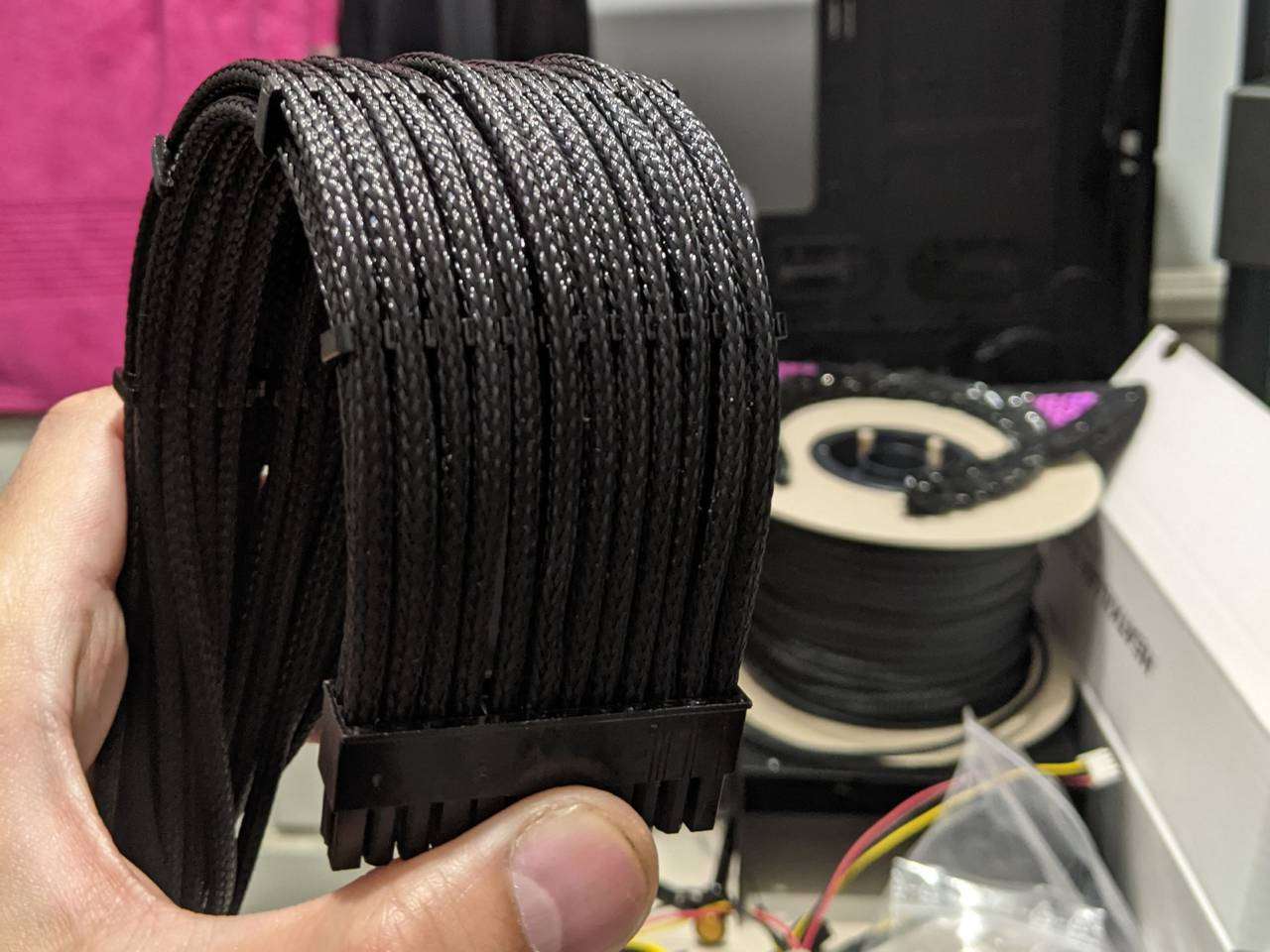
4-pin ATX12V and 8-pin EPS12V
I started with the simplest cable runs to get the hang of releasing the cable terminals from the white plastic connector, sleeving with black adhesive-lined heatshrink at the PSU end and heatshrink-less at the connector.
One thing I learnt quite quickly was that pinching molten plastic between finger and thumb leads to a very sore finger and thumb, on account of them being nearly burnt repeatedly. Later, I discovered that it was fairly easy to achieve the same pinching/pressing action by squeezing the molten sleeving (with temporary clear heatshrink around it) between the casing of the cigarette lighter and the metal frame of the desk at which I was working, saving my fingers and thumbs for the fun of slight friction burns instead, when pulling the sleeving tight.
The 4-pin ATX12V went well, despite the sore finger/thumb, so I moved on to repeat the same process on the 8-pin EPS12V.
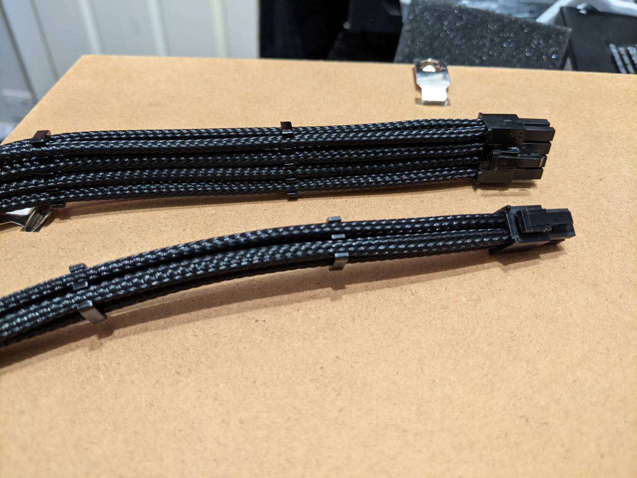
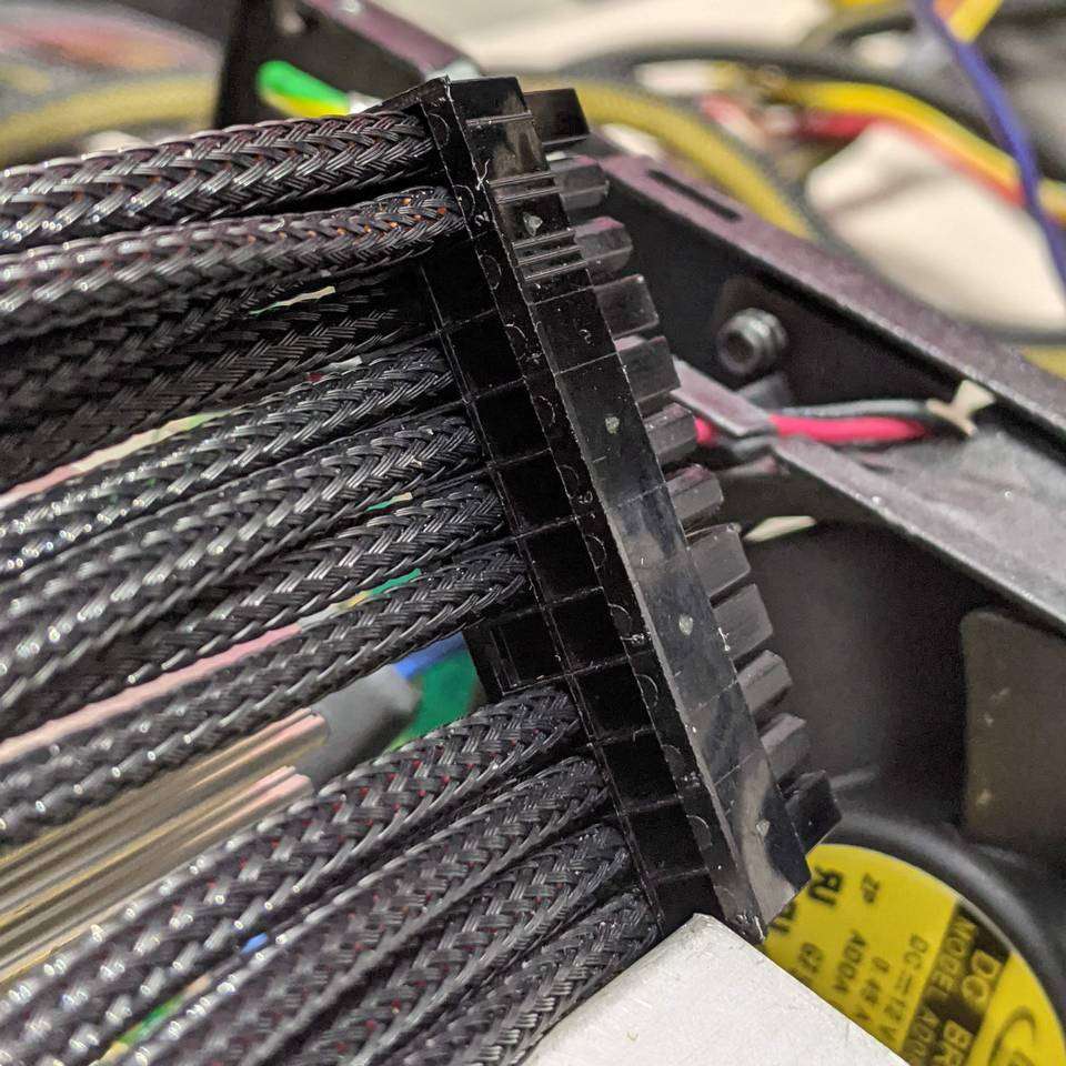
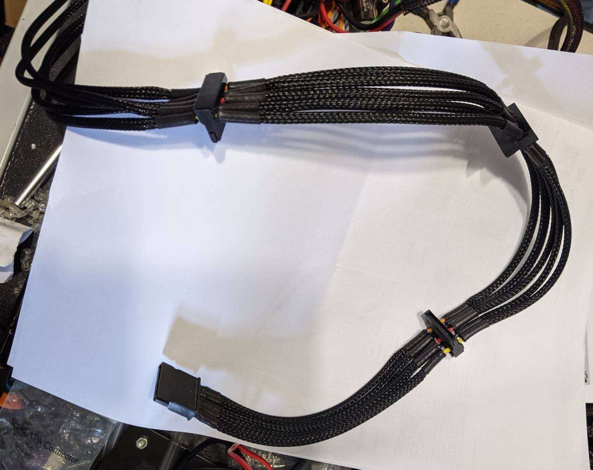
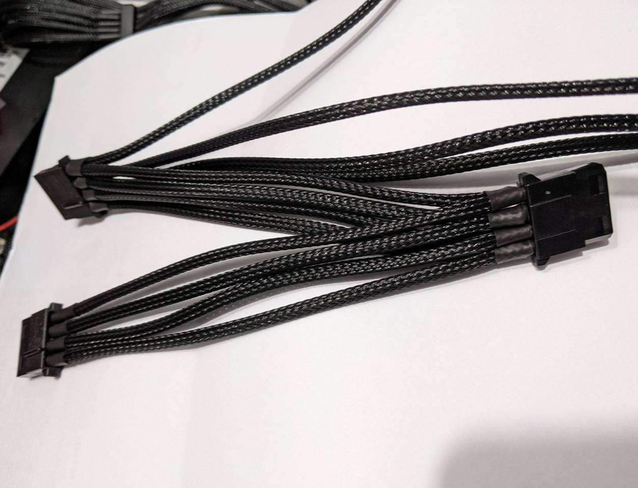
With cable combs installed between the sleeved cables, you can see how the group of cables can be made to maintain a straight or curved shape.
This type of connector is from the family of Molex Mini-Fit Jr, and another variant is the 24-pin for the other power connector to the motherboard, so I used the same technique again, just with twice as many cables as I’d done so far!
24-pin ATX
This 24-pin connector actually has 3 positions with doubled cables. Presumably this is to provide more current handling than a single cable, but this was going to make things a little trickier.
The other side of the connector thankfully had no more doubled-up surprises and a single position (-5V) empty.
Here you can see a closer view of how the heatshrink-less sleeving technique looks at the connector.
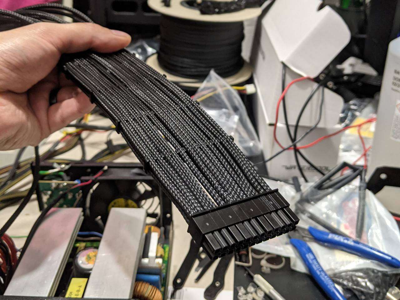
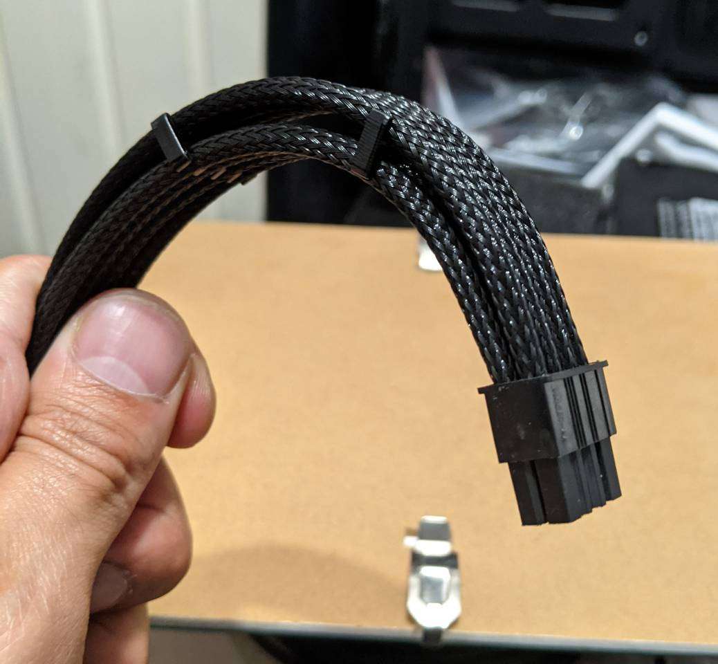
I was impressed by how well the sleeved cables can hold their own weight when suspended in the air.
The cable assembly can also be easily convinced to maintain a curved shaped without being a spaghetti mess. Some cable combs help here, and the most common type with open sides allowed the doubled-up cables to look respectable.
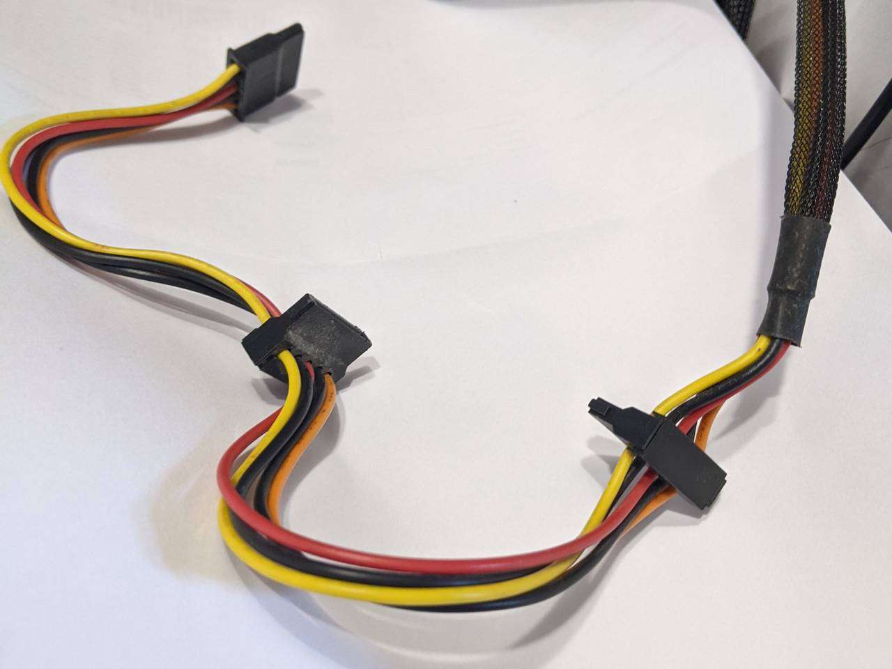
SATA power (recon mission)
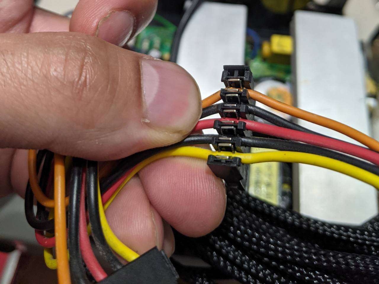
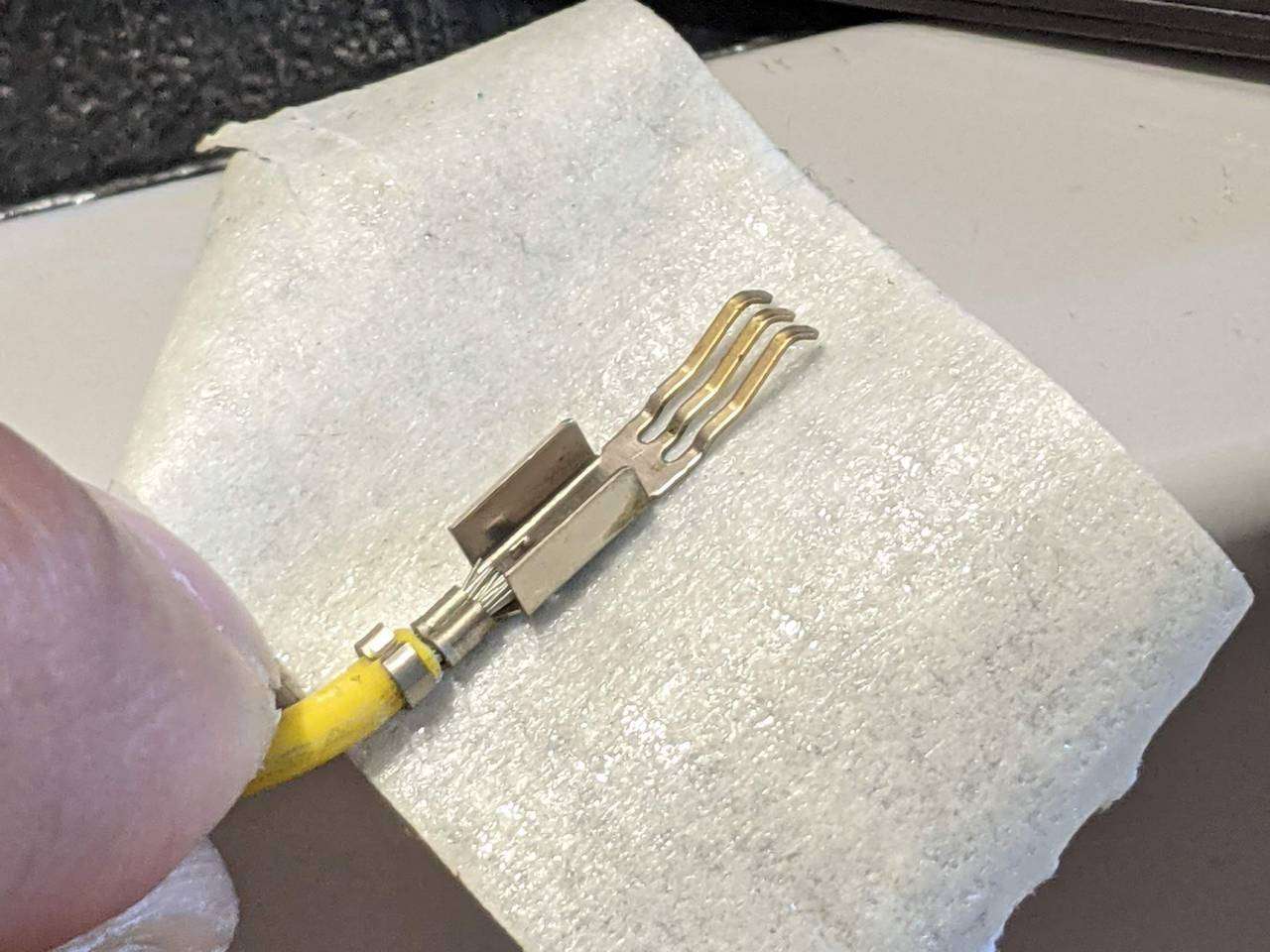
This PSU has the SATA power cables runs with the intermediate connectors that you can pop the cover up to reveal the punch-down style terminals for each cable. There were two of these intermediate connectors on each SATA power run.
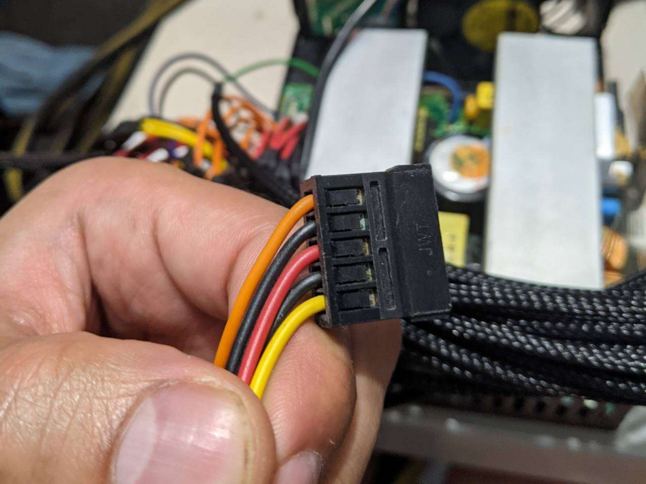
The SATA power connector has the cables enter into connector housing.
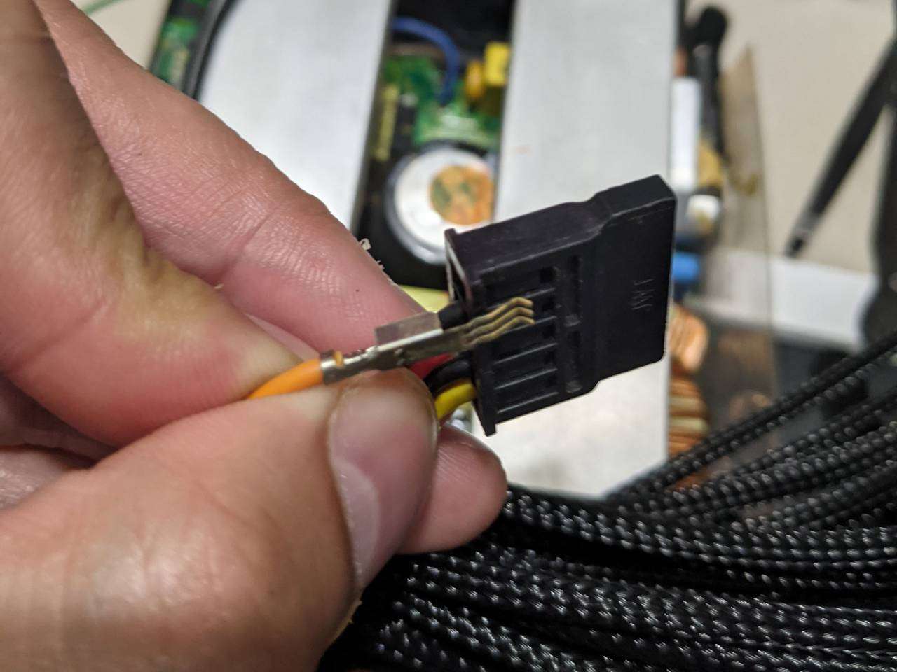
Each cable has this multi-prong terminal on it. After looking at the two cable runs, six connectors, and awkward (to get through sleeving) connectors, I decided to leave the SATA power “fun” until later.
PCI-Express
The “Quad SLI” bit of this PSU comes in the form of 2x 6-pin and 2x 6+2-pin. Each had three 12V and three grounds, with the +2 bit just being two short ground cables daisy chained at the connector end.
Most graphics cards these days use 8-pin power connectors, so I decided to convert the four PCIe power runs to three 8-pin.
Each 8-pin PCIe connector requires 3x 12V (yellow) and 5x ground (black), so 9x yellow and 15x black to make three 8-pin PCIe cable assemblies. The stock 6-pin PCIe cable assemblies have 3x yellow and 3x black, so stock was 12x yellow and 12x black.
This meant I had three too many yellow and three too few black cables.
After much hmming and hahing, I decided to cut three yellow PCIe cables off near the PCB and spied some likely contestants.
At first, I thought I could just rustle up some suitable gauge black power cable and use that for the three extra ground leads, but then considered the fact that the PSU came with three cables runs with the 4-pin fat Molex connectors (a total of eight of them!) and that I’d probably only a few of these connectors ever. These cables runs had a ground that Y-split near the CPU, which I suppose can’t carry as much current as separate cables, but as the “+2” ground pins on 6+2-pin PCIe are just daisy-chained from the other ground pins, using these as my donor grounds in place of the “+2” seems fine as it will be able to carry more current than stock.
I carefully used side-cutters to trim three of the 12V PCIe cables down near the PCB.
Those of you paying attention so far, in what I fear may be a potential bore-fest of cable conundrums, will have noticed that I only had two donor ground cables at this point. I managed to scavenge another ground from a modular PSU cable and set it up for soldering.
If you’ve ever tried to solder power cable with an electronics soldering iron, you’ll know how tricky it can be to get the solder to flow. Mine is only 50W variable I think, so I got it this good. Usually when I try to get the solder to flow more I end up melting the cable insulation! I put some heatshrink over the solder joint and called it a day.
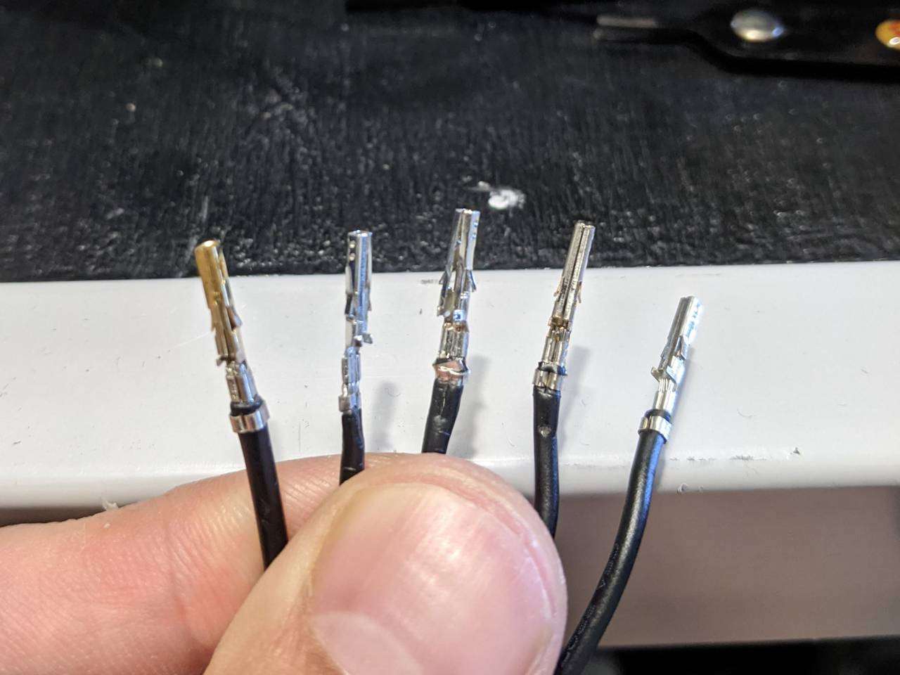
There is an official Molex crimping tool for these Mini-Fit Jr terminals, which probably makes it really easy to add a terminal to a cable, but also costs £120. MDPC-X also offers a crimping tool for a lot less, but it looks pretty similar to the crimping tool I already own, so I just decided to use my existing tool. Above are (from left to right) one donor, two new crimped, and two original PCIe grounds.
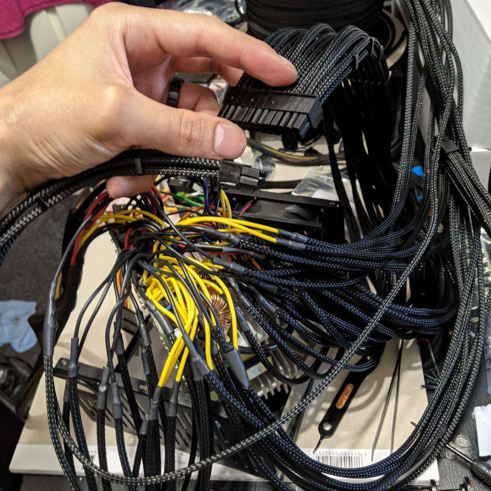
After doing all the PCIe cables, the PSU end was starting to look like it might be a bit crowded what with all the extra sleeving and heatshrink.
SATA power (for real this time)
The remaining cables were just for SATA and the 4-pin “fat Molex” (and 1 floppy) power connectors, so I decided to return to tackle the SATA cables with the awkward connectors.
I wrapped each terminal with masking tape to help it avoid snagging the braidesh mesh of the sleeving.
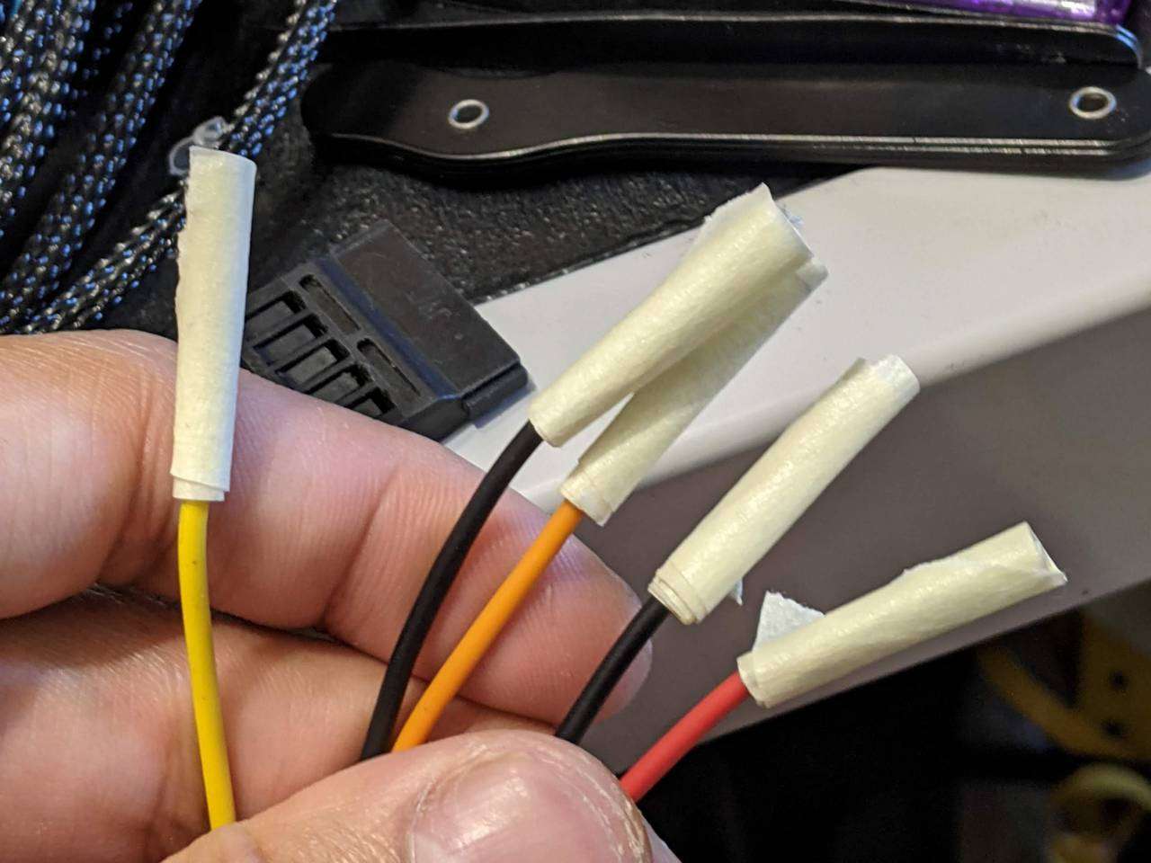
For the intermediate connectors, the cables go through the housing so I had to use heatshrink here as the sleeving can’t easily be made to stay up to the connector by itself. Lutro0 mentions using superglue for heatshrink-less sleeving SATA power cables in some of his client builds, but that sounded like a massive hassle, I didn’t have any superglue at home and these cables would be in the rear chamber of my PC case anyway so I didn’t really care too much if these had heatshrink visible. I just made sure to cut them as close to dead-on 15mm as I could get so that they’d at least line up reasonably well with each other.
And here’s the end result with the heatshrink. I also used heatshrink on the end connector for a more consistent look.
Here’s what other SATA power looked like before resleeving.
“Fat Molex”
There is an official name or part number for this type of connector, but what most people call a “Molex connector” is one of the fat 4-pin connectors that plug into IDE (and old SATA) hard drives and optical drives.
I used my experience with the SATA power cables to do a heatshrink-sleeved method again.
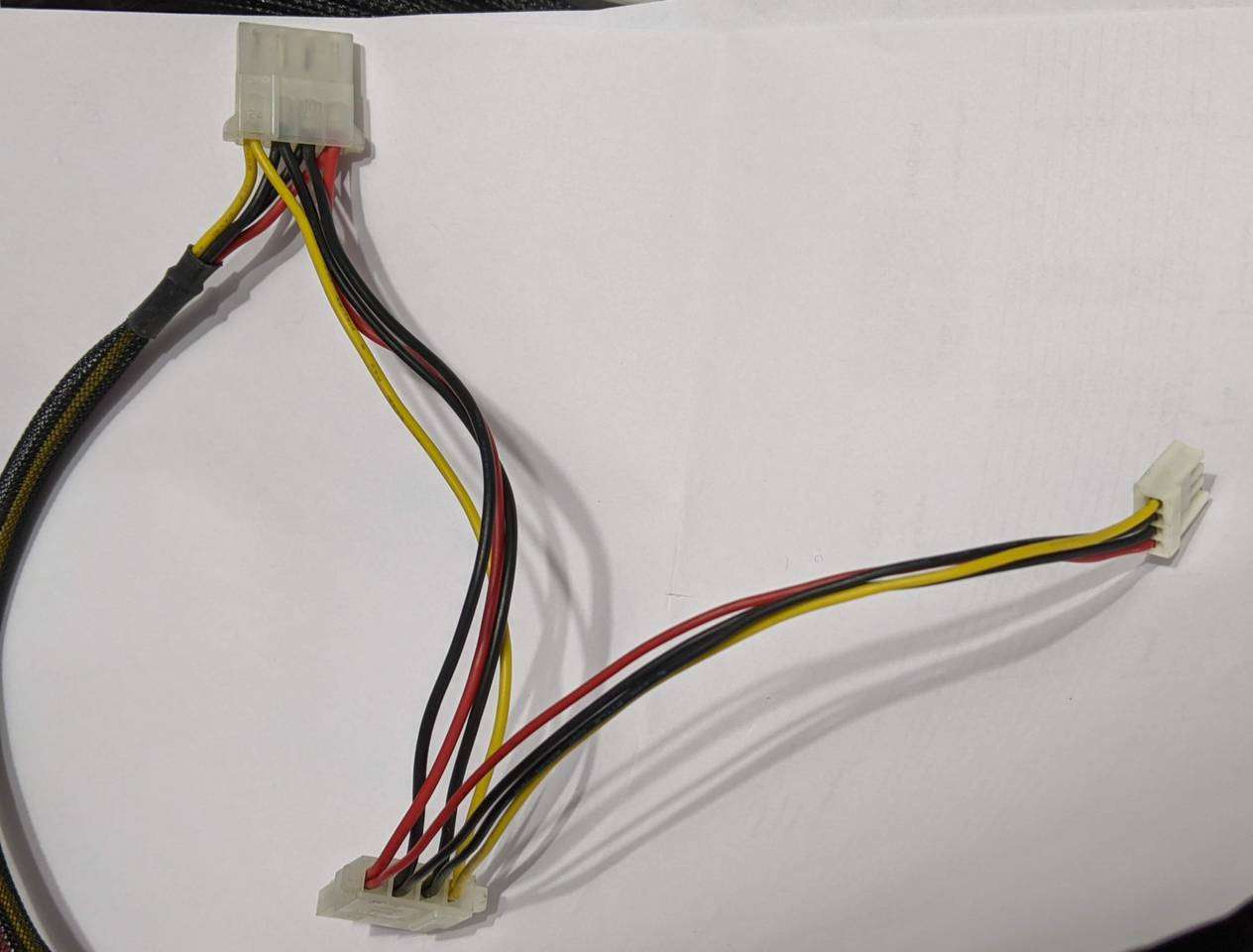
It almost seemed redundant having a 4th and 5th fat Molex, as well as a floppy drive power connector, when I’ll probably only use two fat Molex connectors for my water pumps. But I thought I may as well sleeve and keep them rather than cutting them off, in case I needed them for something in future.
“That type of flying thing from The Matrix”
After literally days of doing this resleeving mod, my wife said it looked like I was trying to make a wig that looks like one of those flying things from The Matrix. She was of course referring to the Sentinels.

The resemblence had not escaped me and we had a laugh about it. She’s very funny and definitely my one.
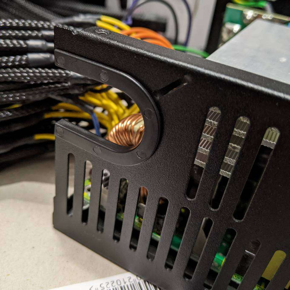
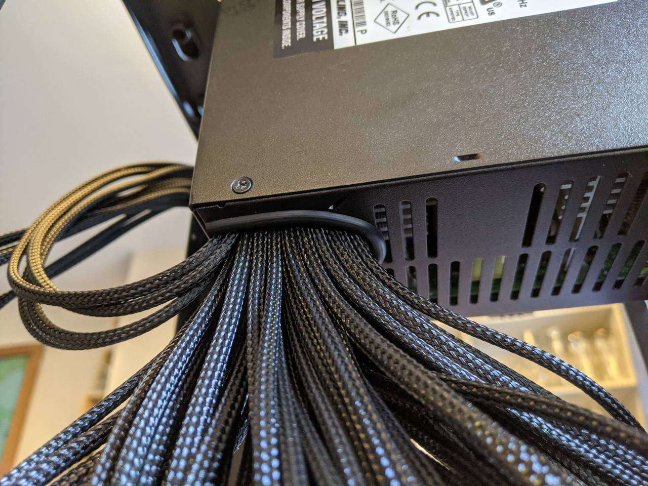
PSU case cable entry
The bundle of power cables used to enter the PSU case via a single opening. I needed to enlarge this opening as the mass of individually sleeved cables was a bit bigger than when they were sleeved in bundles of cables.
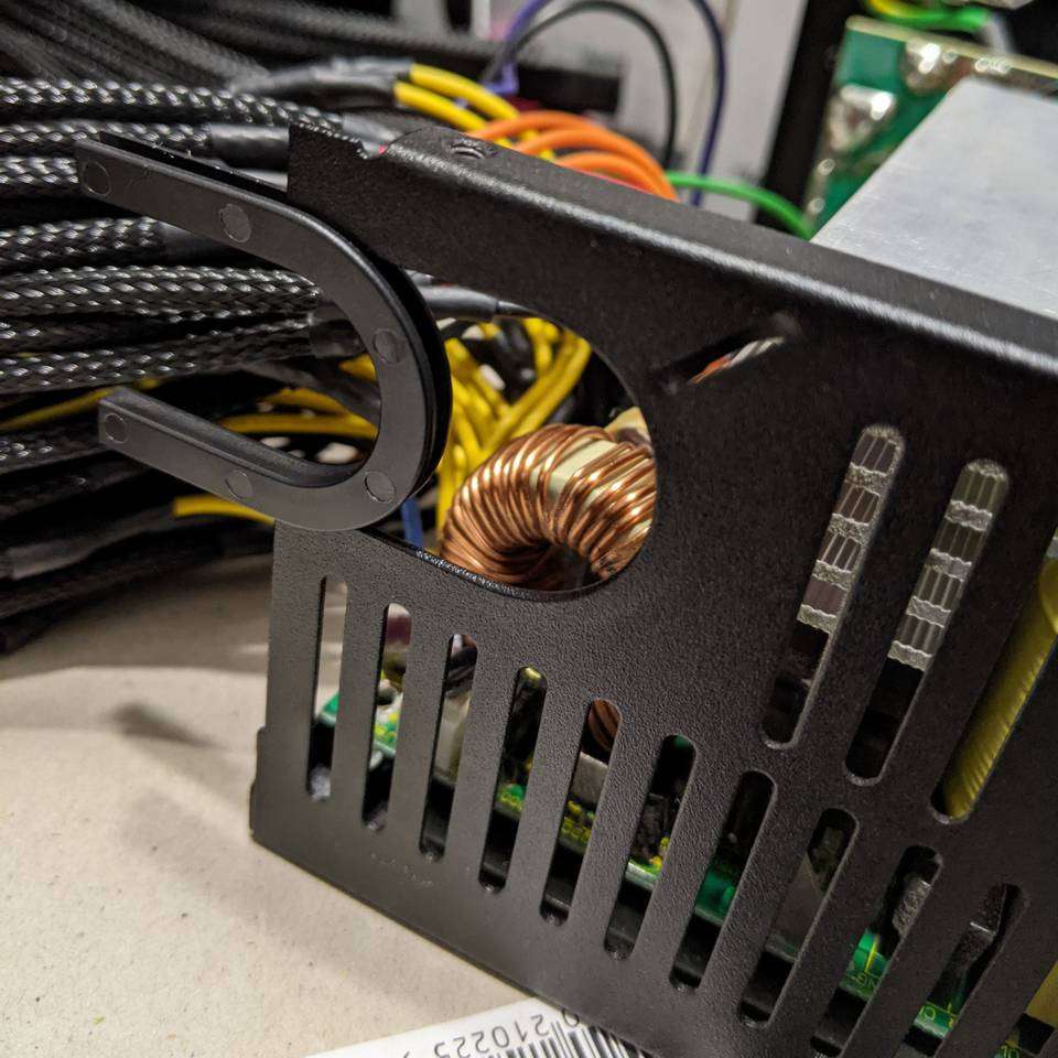
The plastic part slides out.
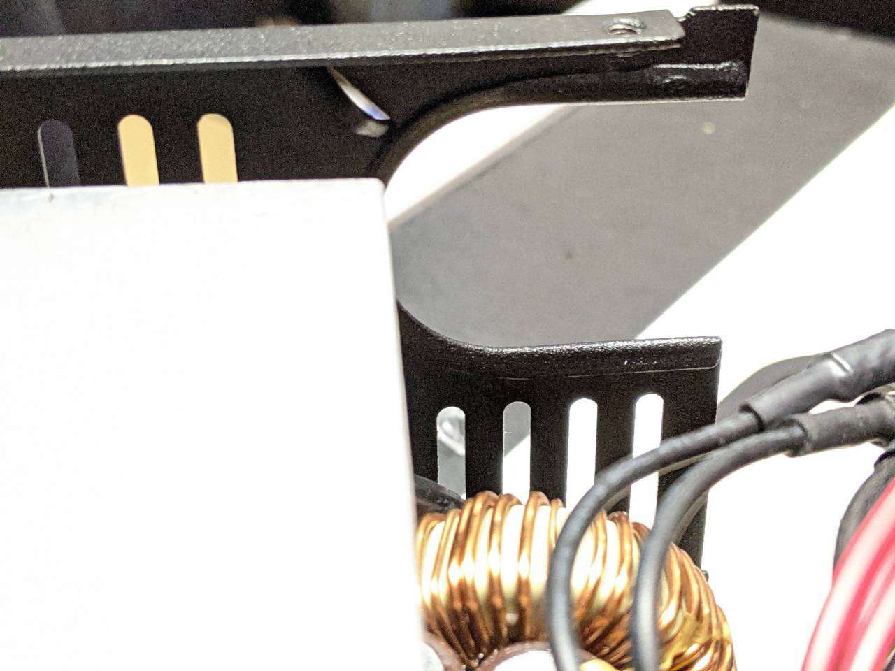
From the inside, you can see that the casing is rolled and flattened around the opening.
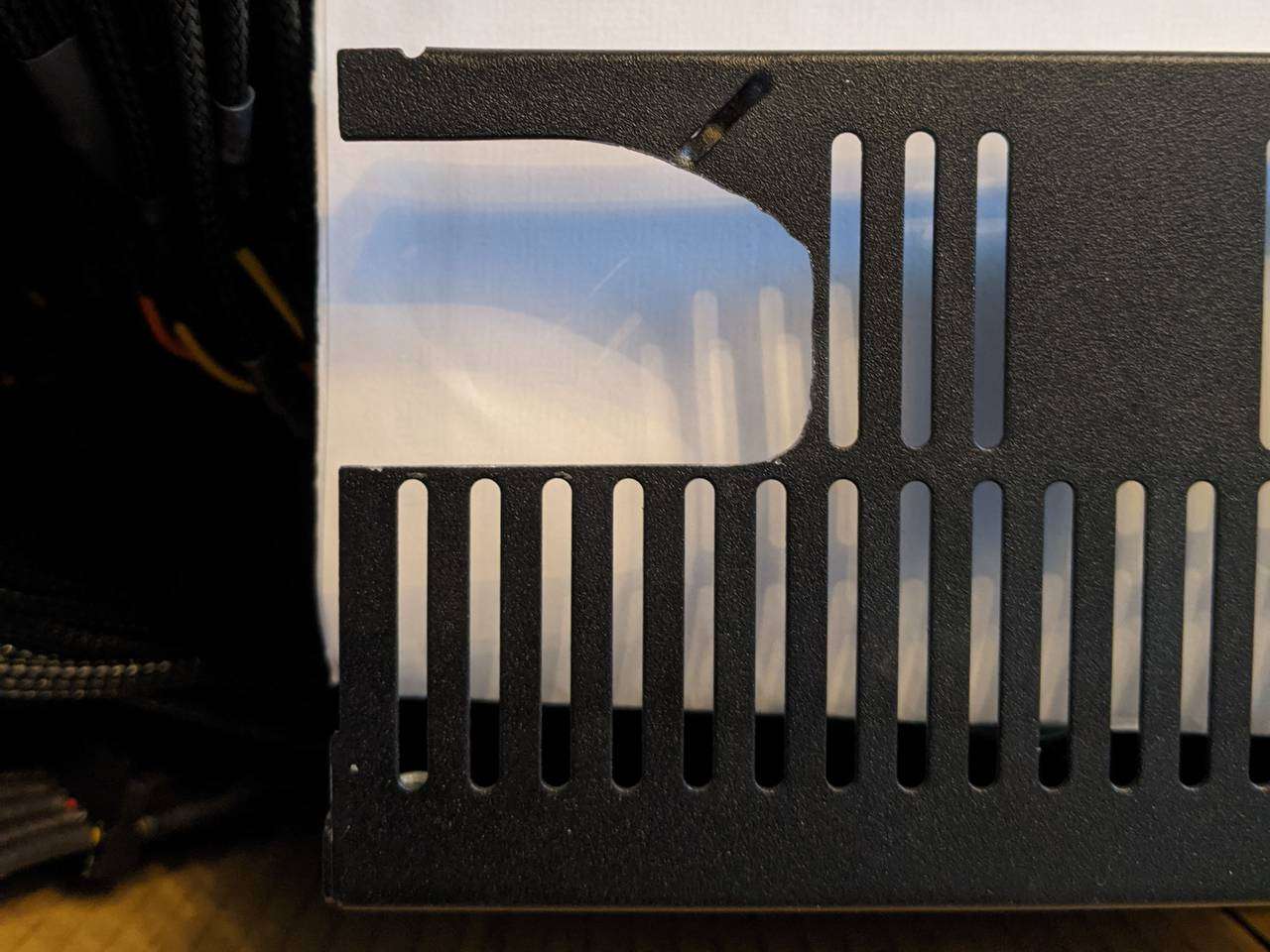
I used a jigsaw with a skinny blade made for tight corners and cut the hole a little larger, whilst trying to maintain the integrity of this area as well as the cable binding loop just above the opening.
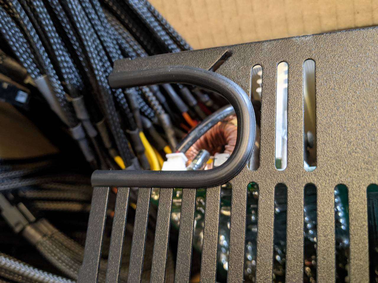
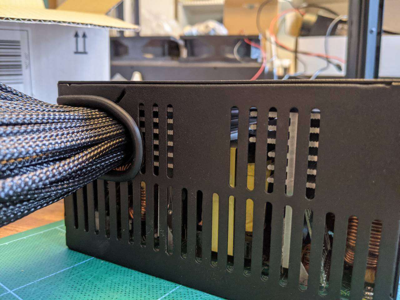
The plastic pinch protector was replaced with some rubber edging strip.
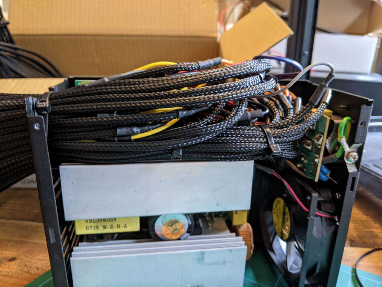
It was a bit fiddly to get the groups of cables distributed in the void where they originally lived without sleeving inside the PSU case, but after some (actually a lot of) adjustments this messy of cables pressed down to a size that made it possible to get the PSU case cover back on.
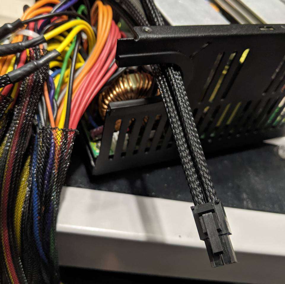
Test fitting in the PC case
I had already bought the Thermaltake Level 20 HT case for my new PC build, and the PSU is installed in the rear chamber, unconventionally hanging from the top due to the case design.
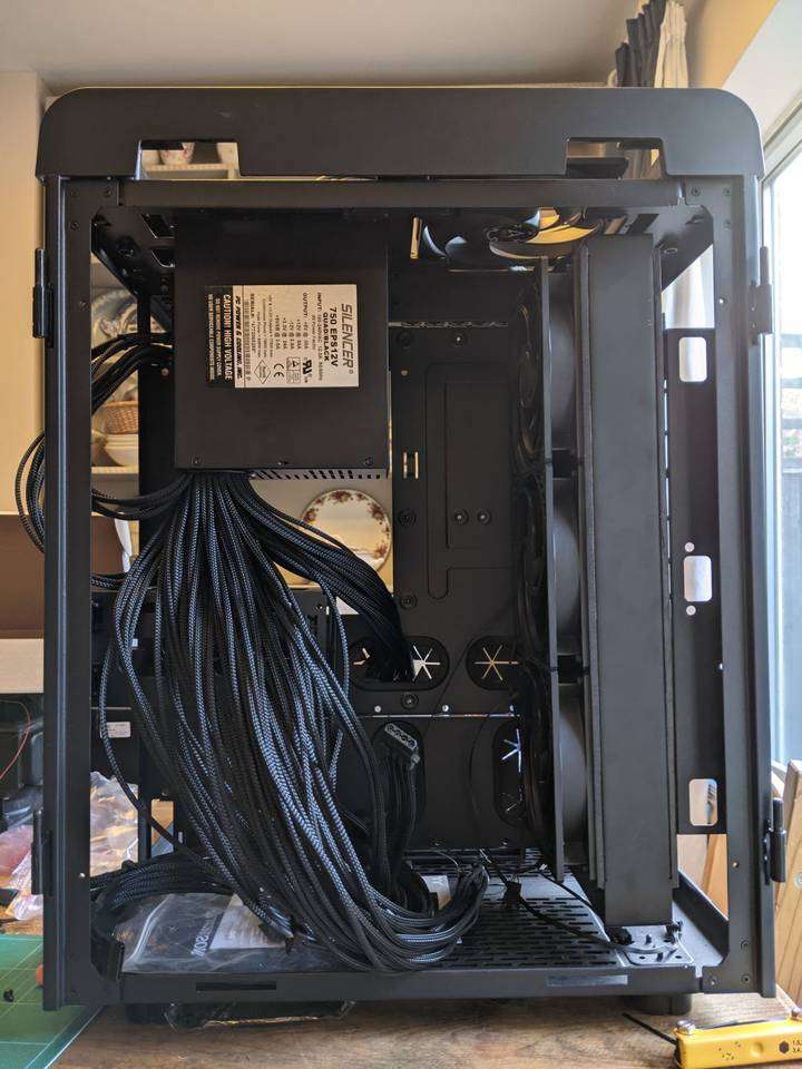
The PSU mounting plate can be oriented 90°, 180° and 270° from the orientation you see now, so here I was seeing which direction worked best for the 24-pin, 8-pin and 4-pin motherboard power connectors.
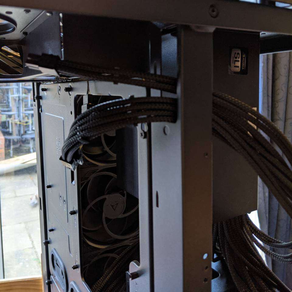
The supplementary motherboard connectors can use this pass-through hole in the case chassis to easily reach that area of the motherboard.
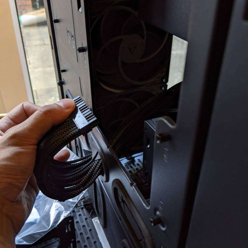
The main motherboard power connector can also easily reach the corresponding area of the motherboard.
Final thoughts
I’m happy with how this turned out, but this is definitely in the list of “things that I would rather not do ever again.”
It took about seven weekday evenings and a weekend to do this non-modular PSU sleeving mod. Maybe that’s because it’s the first time I’ve attempted individual sleeving, maybe I took longer to take care to get it done as near to perfect as I could, or maybe (most likely) it just takes a really long time.
A few people have asked, “is it worth it?”
For most people, you probably would (should?) just buy a new modular PSU with the cables already individually sleeved, or sleeve/resleeve the modular cables, or get sleeved extensions for the cables visible in your build.
For me, I already owned this decent 750W PSU, wanted it to look better, like modding things, and wanted to save some money (to put towards other parts of the build) by just buying the sleeving supplies rather than buying a whole new PSU. Also, the Thermaltake Level 20 HT case has three side panels that are entirely glass, so it’s a bit of a show case where everything needs to look good and there are only a few small areas to stuff-and-hide the cables.
My power cables will be visible, but they’ll be neat and look great, so I’m already happy :)
Stay tuned for more modding madness in this PC build worklog series!