


After modding the case with holes for the pass-through fittings and reservoir brackets, and putting the components back in, I was ready to take on the task of connecting the water cooling parts with tubing. I decided to use acrylic hard-line tubing for this build, as I like that it looks similar to glass and is more resistant to staining, clouding and scratching compared to PETG.
Rather than buy expensive tubing branded for PC water-cooling, I bought some from a UK supplier (Kitronik) that carries plastic stock material, as I’d measured up the total length of tubing needed and with a healthy extra amount to allow mistakes I estimated I’d need around five metres of tubing.
In previous water-cooled builds, I have used soft tubing with barbs and hose clamps, so this was my first attempt at using hard-line tubing and compression fittings. I made sure to watch plenty of YouTube videos showing the technique of using a heat gun to bend acrylic hard-line tubing, and took some time to work out how many fittings I would need and made a big order from AliExpress.
Barrow fittings
After looking at the different brands/manufacturers of water-cooling fittings from the likes of Bitspower, EK, etc., I came across Barrow fittings and liked the look of them, the range of fittings they make, and found they are regarded as decent fittings throughout the water-cooling community. They’re significantly cheaper than Bitspower and EK, so with the amount of fittings I wanted, it made a big saving in cost. The only fittings which aren’t Barrow are the Bitspower G3/8” to G1/4” adaptors I needed to convert the Thermochill PA120.3 radiator ports to the modern standard of G1/4”.
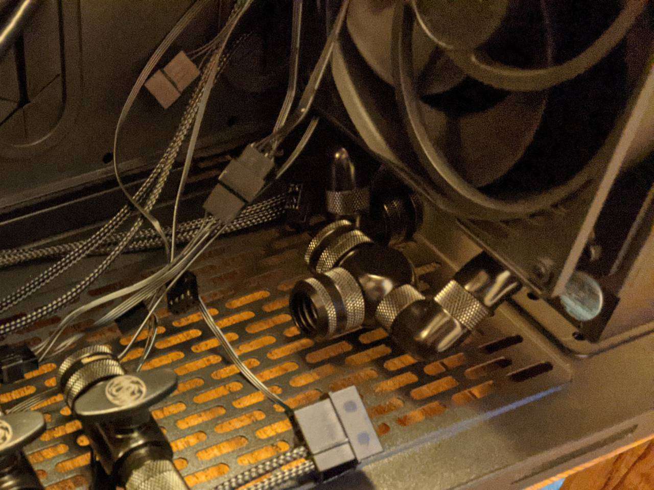
Fittings for GPU loop radiator and drain
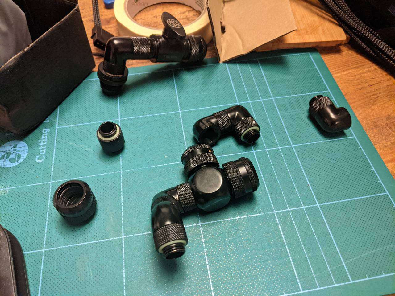
I ordered plenty of fittings including stop valves and angle adaptors to allow me to combine them into solid mounting complex pieces. This included for routing underneath the vertically mounted EK CE 420 radiator for the GPU loop. One of these sections includes a T-junction piece that will have tubing leading to what you can see at the top of the photo above that resembles a water tap/faucet. This stop valve section leads to a pass-through fitting mounted in the base to act as a drain port.
Fittings for CPU loop pass-throughs and drain
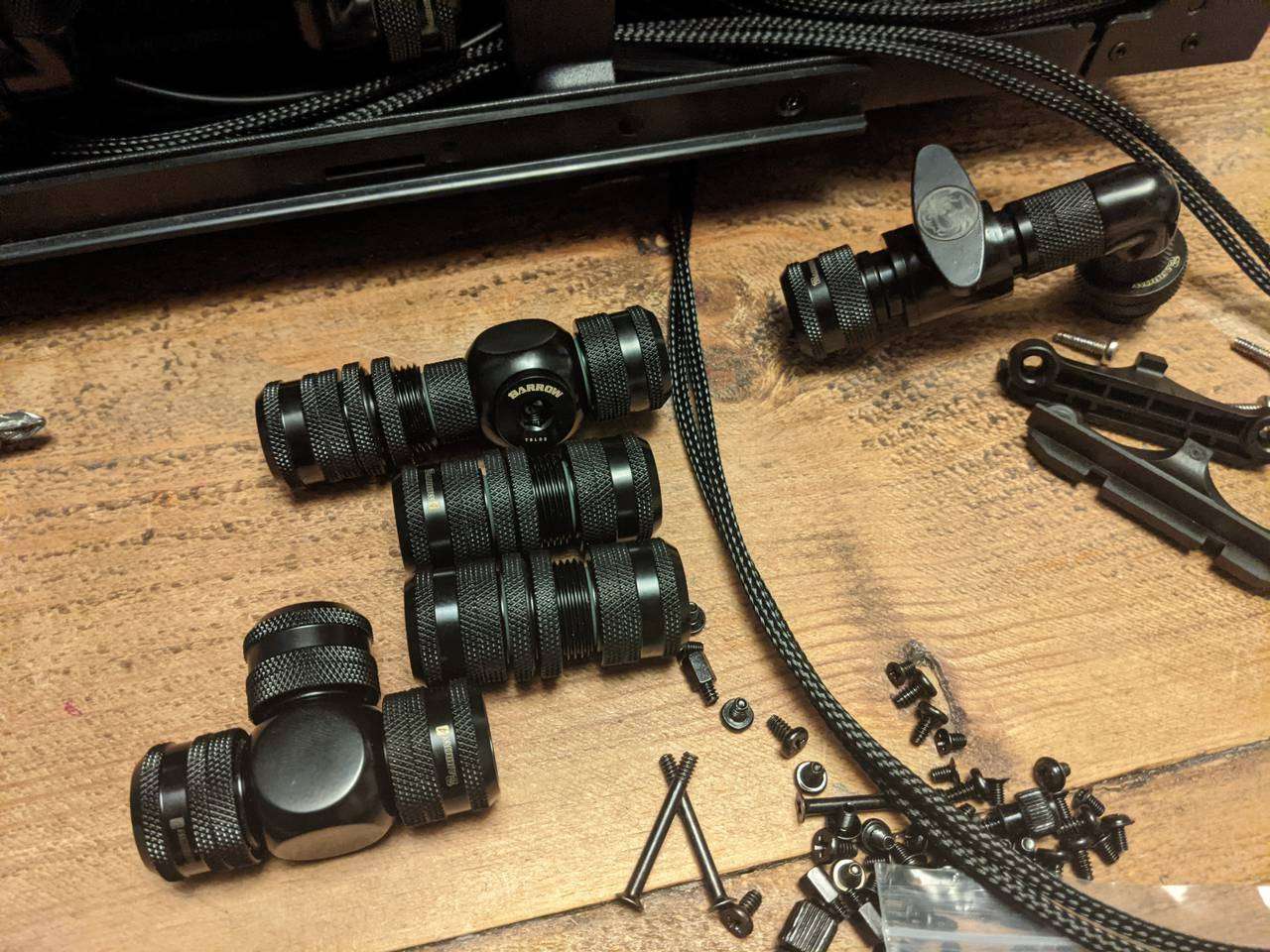
Each of the pass-through fittings that will be mounted in the case’s bulkhead needs a compression fitting on either side to allow tubing to be connected. The top one will also have a T-junction with a stopper to act as an air bleed for filling/draining. I made another tap/faucet to act as the CPU loop drain, and for the CPU loop there is a more simple T-junction to provide the route to this drain port.
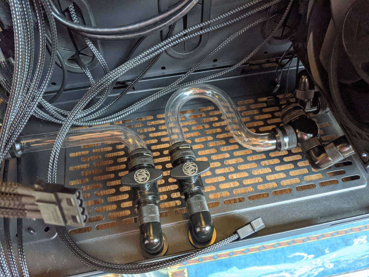
Drain ports
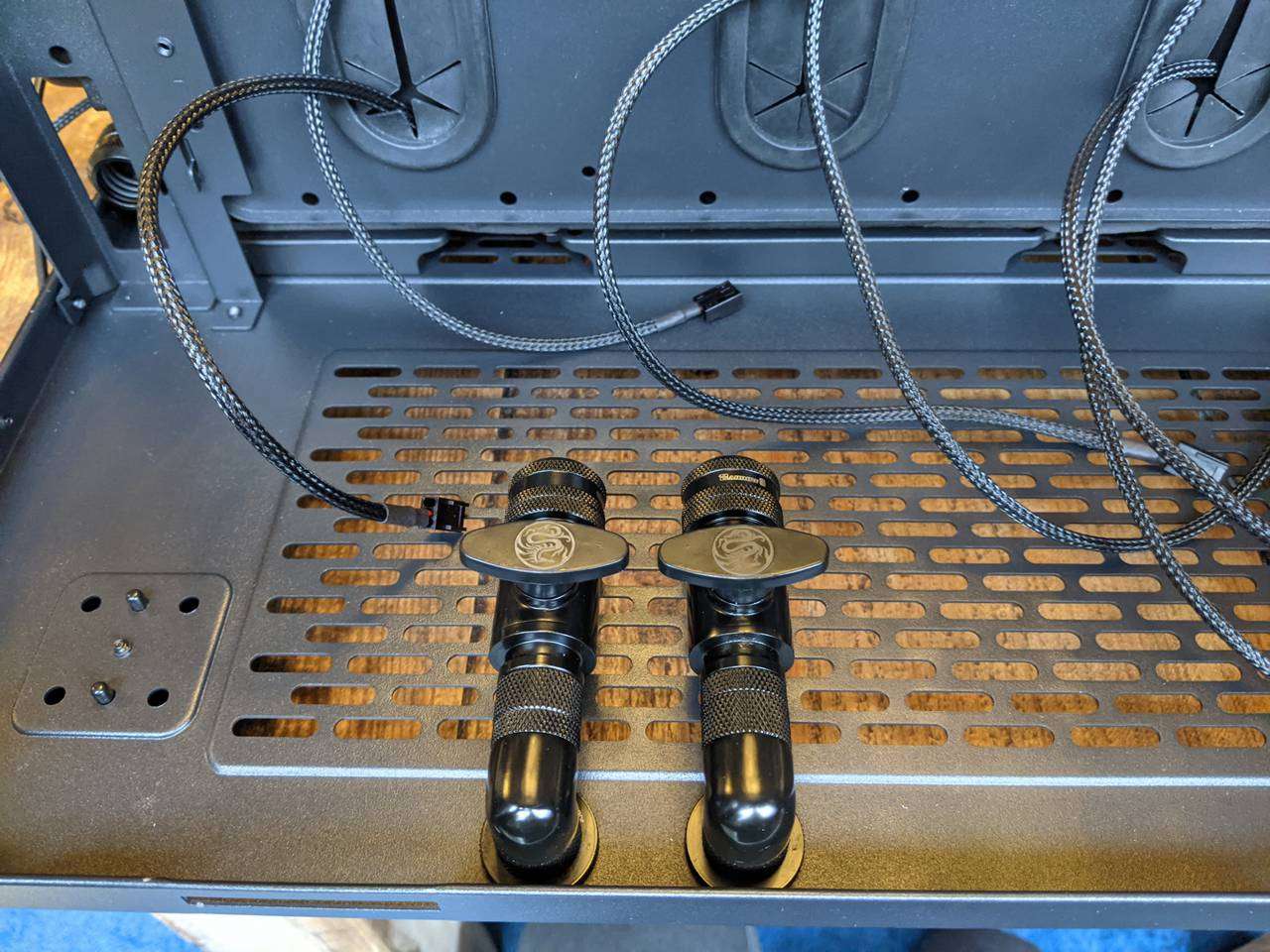
Anyone who has built a water-cooled PC will know it is often tricky to fill or drain a water loop (or both!) So for this build I wanted to have a nice easy option to drain either loop, and have the drain ports (with stop valves) mounted securely to the case. Here they are mounted right at the back of the rear chamber.
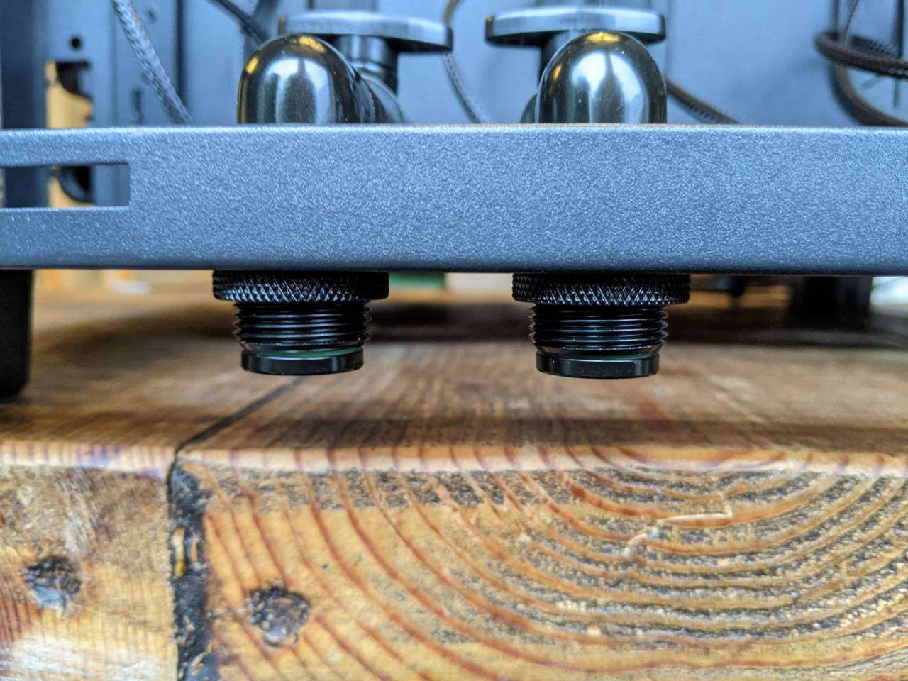
The pass-through fittings protrude below the case floor, but the Thermaltake Level 20 HT case has tall enough feet that the stoppered fittings do not touch whatever the case is standing on.
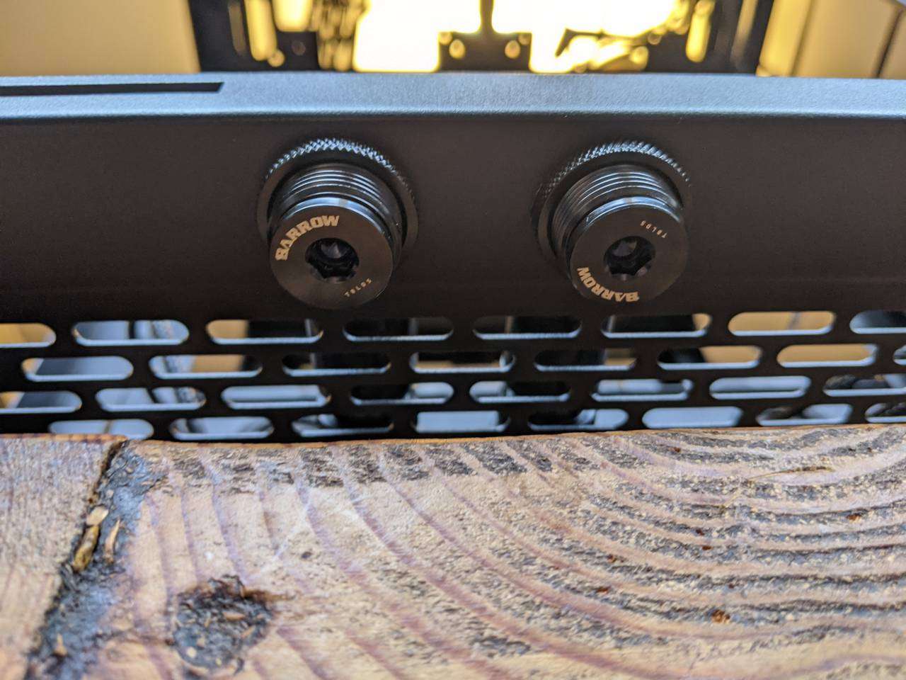
Even though the drain ports have stop valves, I wanted to be sure that any remaining liquid didn’t drip out onto the desk/table. These hex-holed stoppers seal up the drain ports when not in use and will prevent accidental draining if the stop valves are inadvertently knocked open.
Also, you can see here that the drain ports can hang beyond the edge of the desk/table to allow easy collection in a bottle. With the stopper off, it is just a G1/4” threaded pass-through fitting, so I could even attach a barb and soft hose leading to a bottle/bucket on the floor if I wanted.
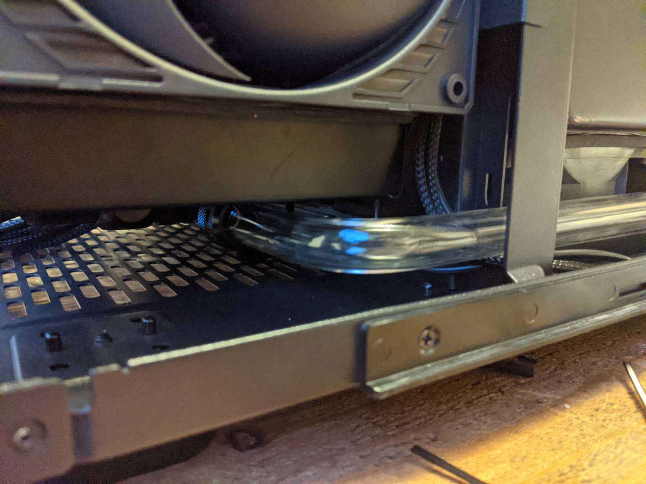
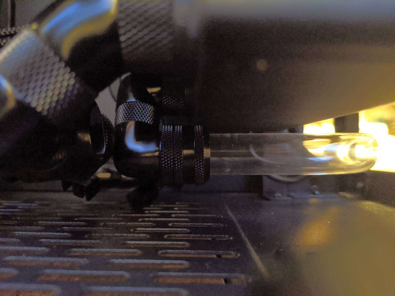
GPU radiator fittings installed
Here are a couple of the previously shown combined fittings installed on the EK radiator. The far one is two 90° angle adaptors and a compression fitting that will serve as the GPU radiator’s inlet. The nearer one is the outlet with a T-junction to lead to the GPU loop’s drain port.
Acrylic tubing
I set up my heat gun on a sturdy freestanding wooden shelves unit with the heat gun pointing up, and the heat gun clamped to the shelves unit to be sure the heat gun would stay in place and not fall over (just in case I kicked the shelf unit or snagged the power cable or something).
The first attempt at bending the tubing was a failure. I heated up the tubing too fast and it had many bubbles inside the plastic as a result. My heat gun only has two heat settings and I was already using the lowest setting, so I knew I had to regulate the gradual heating of the plastic by keeping the plastic at just the right distance away from the heat gun’s… muzzle? Can a heat gun have a muzzle? It is a gun after all, right? Haha, well the end where the hot air comes out, I’m calling that the muzzle.
After heating the plastic up too fast and ruining a section of tubing, I had a rough idea of how much heat was needed to get to that point, so found it fairly easy to bring the tubing up to slightly bendy temperature a bit more slowly, and then move the tubing a bit further away from the muzzle to heat it ever so slightly hotter until it became very almost floppy. It’s quite tricky to get it to this point, and the difference between rigid, floppy and ruined (yes, very funny, please send me all your jokes about that) is a very fine line that requires a good amount of sweaty brow patience.
Manual pipe reamer made into powered version
After cutting the acrylic tubing (I used a circular saw with a 40 TPI blade that can cut wood, metal and plastic), you need to deburr the cut ends but also bevel the outer edge of the end to taper the tubing in slightly so that it doesn’t slice through the rubber (or are they silicone?) O-rings in the compression fitting.
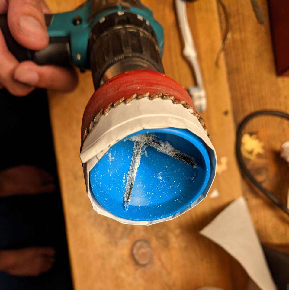
There are expensive tube/pipe reamers available that fit onto drills, and there are the super cheap hand operated reamers that do the same thing but more slowly. I went for the cheap option but, after looking at the shape of it (basically a cylinder), I thought it looked like it would fit inside something to allow it to be used with a drill. I have a bunch of different sized holesaws and one of them was just a bit bigger than the reamer. Some folded paper padded out the gap to hold the reamer securely in place.
This made the tedious task of deburring and bevelling the cut tubing ends much more bearable. It still took a while, but just involved holding the tubing in the reamer and modulating the drill speed with the trigger. Top tip: if you apply too much pressure to the tubing into the reamer, it will start to nibble away small chunks of the edge rather than gradually shave away a perfect bevel. After finding this out, I applied low-medium pressure and just let the reamer gradually bevel the end. It took a while, but it was the drill doing the hard work rather than me!
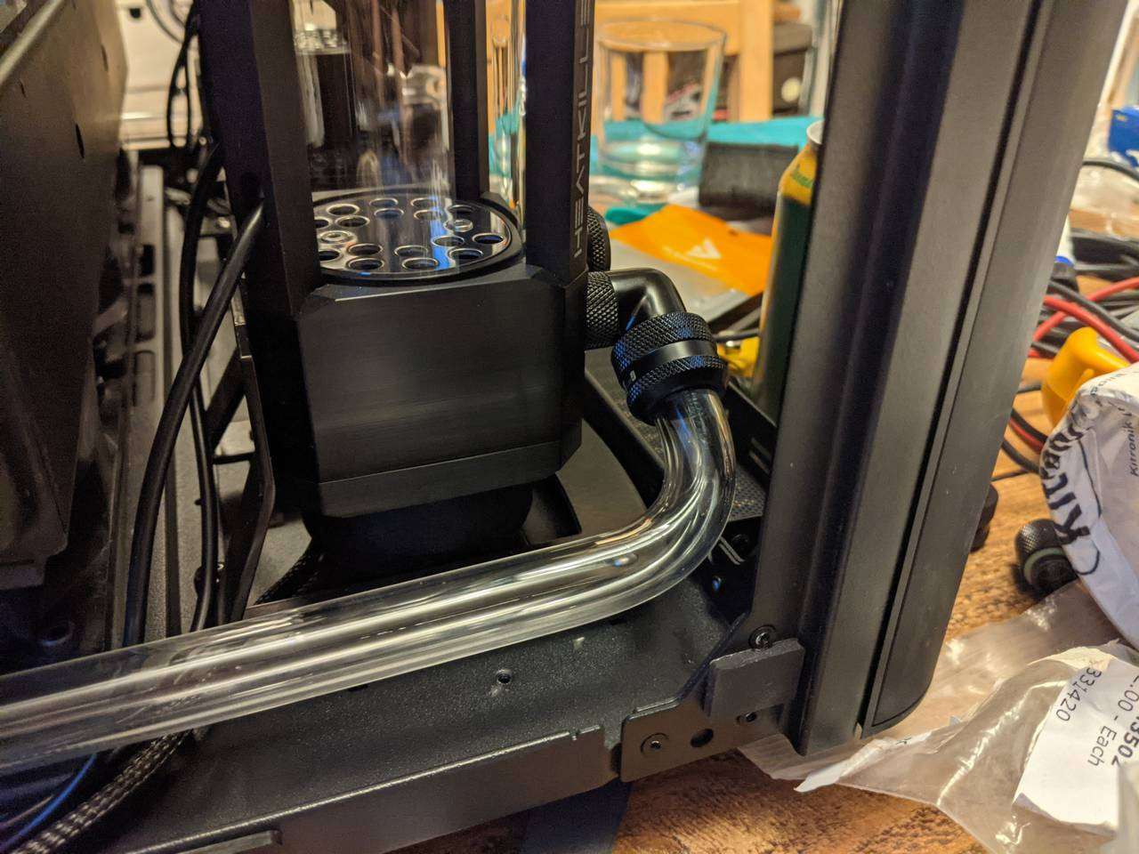
First two tubing sections (CPU loop)
I picked out one of the pieces of 16mm OD (2mm wall) acrylic tubing from Kitronik, and started out bending the tube section that will run from the pump outlet to the radiator (for the CPU loop). I formed the tight bend around a 180° pipe bending guide, but didn’t bend it all the way, to allow it to run out to the side of the case towards the radiator. Then it just needed a slight bend to point it towards an angled fitting at the radiator port.
The pump inlet will take the return from the CPU block, so I took another bit of tubing and bent it 90° back, then 90° up, and then 90° back towards one of the pass-throughs.
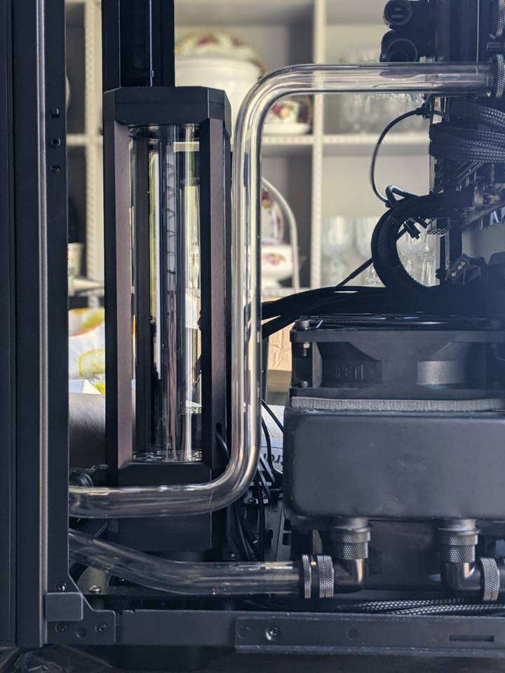
The first attempt I did for the three-bend section between pump and pass-through ended up with a vertical section that wasn’t truly vertical and it stood out like a sore thumb next to the Heatkiller Tube reservoir, so I redid it. I’m pretty happy with the second attempt and glad I took the time to redo a perfectly functional, yet visually jarring, section of tubing. It would have annoyed me every time I looked at it if I had left it noticably off vertical!
CPU block tubing
After jumping straight into the deep end with those two tricky sections of tubing, it was a relief to do the next two much simpler sections that run to and from the CPU block.
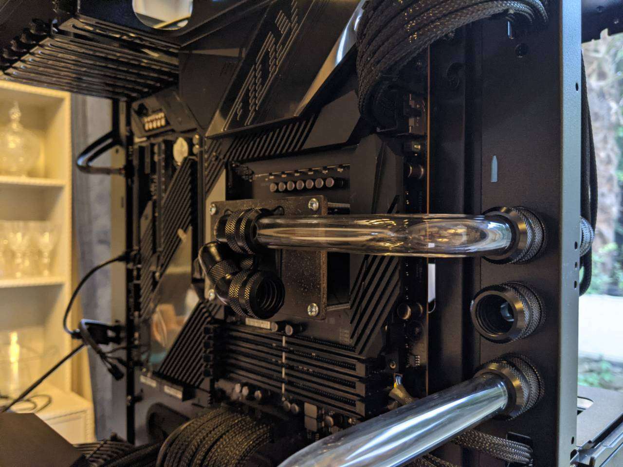
Each CPU block tubing section only has a single 90° bend, but the cuts had to be positioned precisely to allow the tubing to be perfectly square at the bottom of each compression fitting. The first attempt was cut a bit too short, so I had to redo it, this time cutting to allow a tiny bit extra length and then sanded it down until it was the perfect length in both directions.
The tubing was meant to run across horizontally, parallel with the case floor, but it was pretty hard to estimate/measure where this would be, so it’s a bit off perfectly straight, but close enough for me.
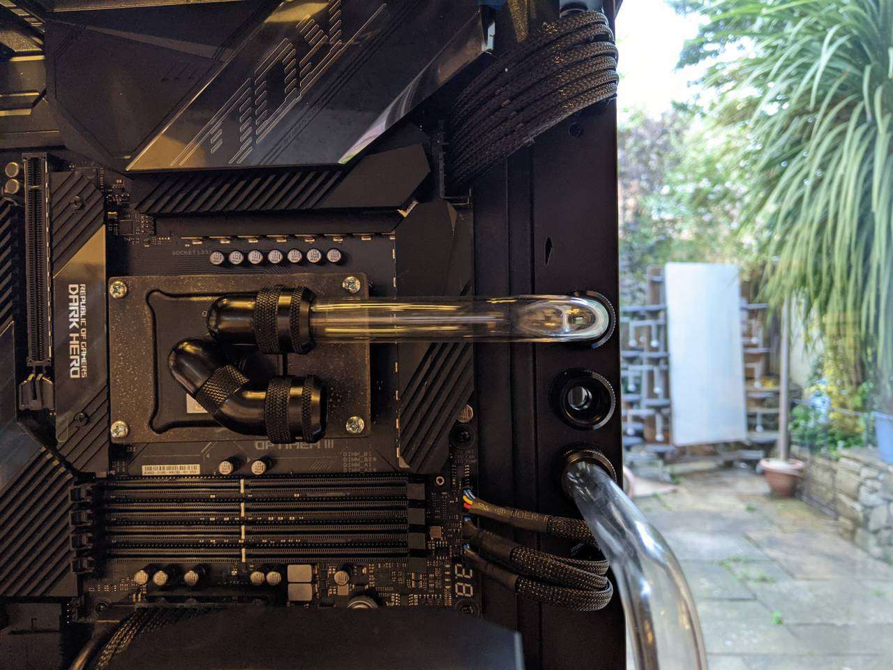
The more important aspect here for me is that both CPU block tubes can easily be removed, after partially draining the CPU loop, to allow adjustments and maintenance of the water block. Also, I ran the tubing this way so that the tubing does not run over the DIMM slots. In previous builds I have had tubing routed over the DIMM slots and it has made swapping out the RAM really annoying, sometimes necessitating draining the loop and removing tubing. In this build, none of that shenanigans is required to get to the RAM.
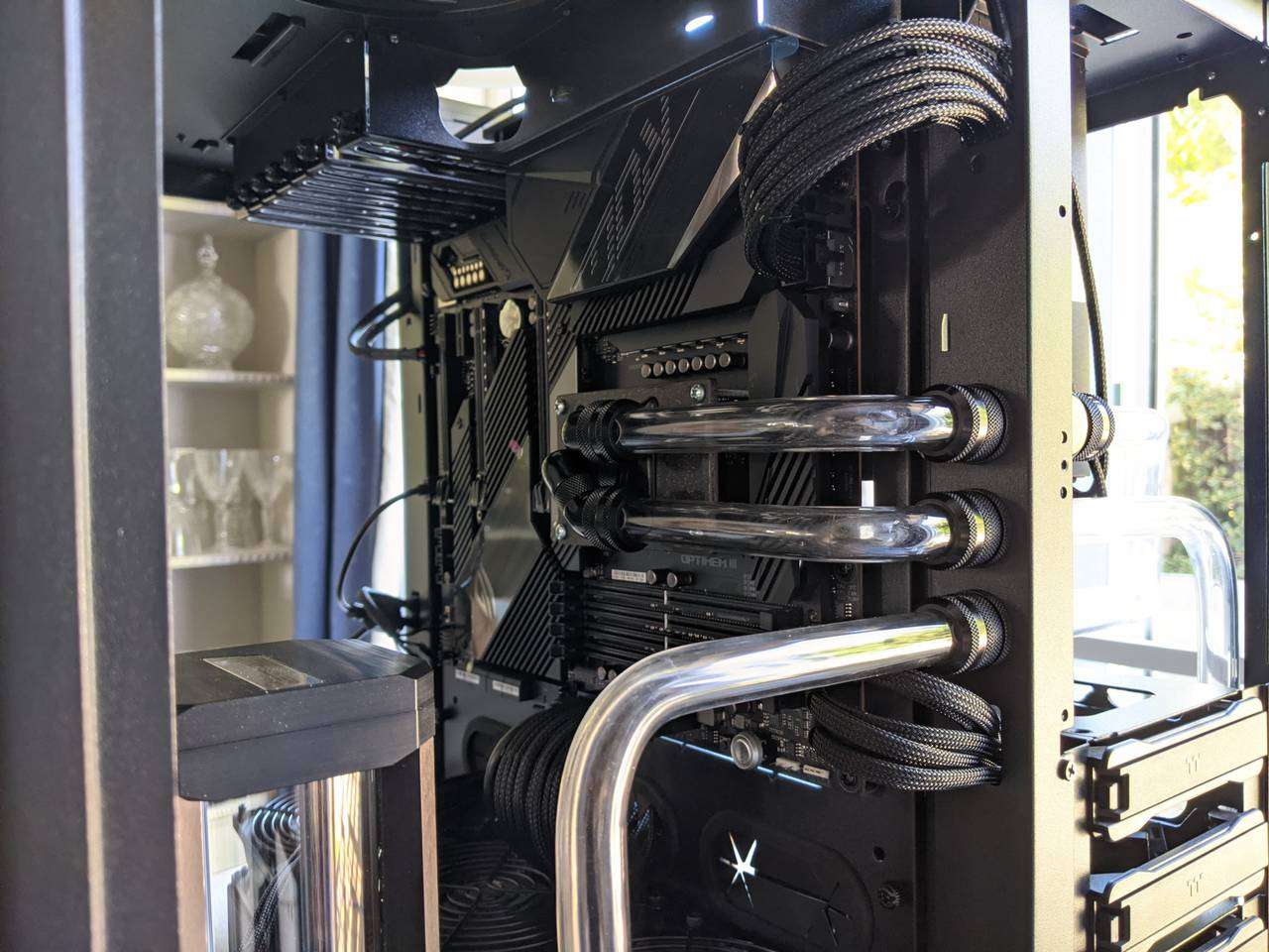
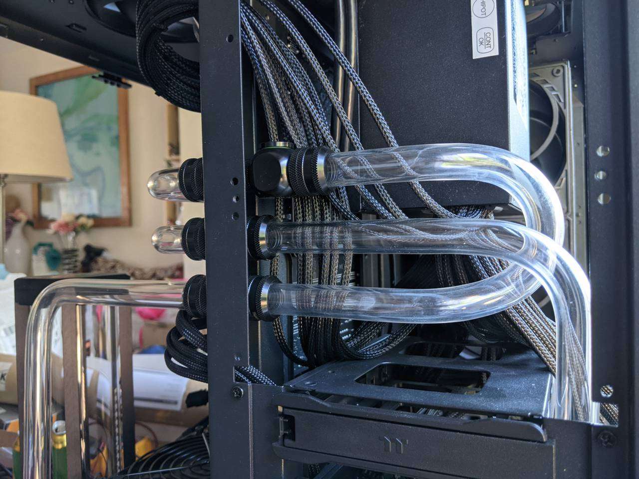
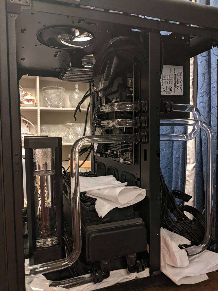
CPU loop rear tubing
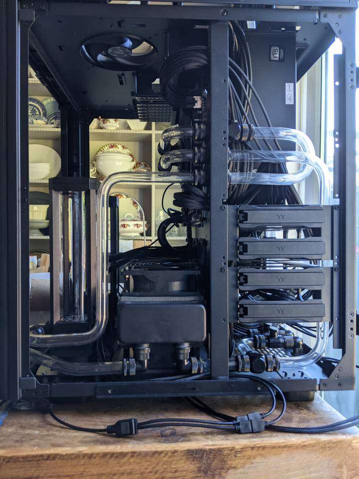
Around to the rear chamber I needed to add more tubing sections. The section at the top with the 180° bend provides a return from the CPU block outlet. Down at the bottom you can see a short section from the radiator to a T-junction. This splits off to the drain port, and also continues up to the CPU block inlet.
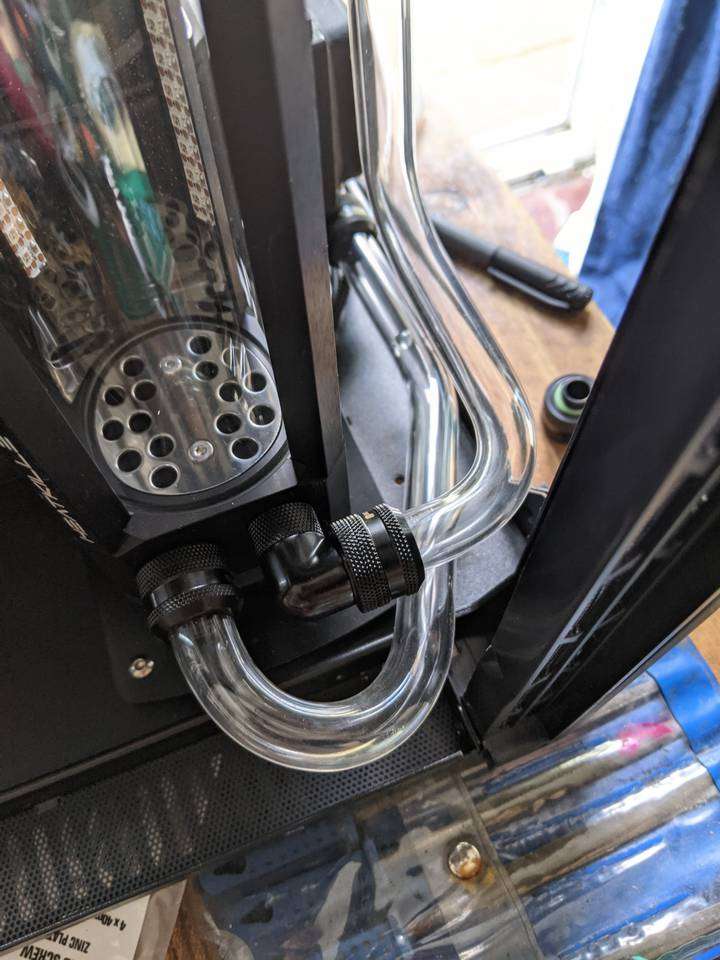
Tricky CPU block outlet return section
Here you can see where the stopper in the top of the T-junction piece will provide an air bleed for the CPU loop. You can also see that the 180° tubing is also bent towards the PSU to provide clearance for the tubing coming up from the radiator to the CPU block inlet. This 180° and two simultaneous bends was particularly tricky and took three attempts. The first attempt I overcooked it and got bubbles, and the second attempt I bent the tubing while it was not quite heated enough and it deformed slightly which produced a slightly kinked bump. This is one of those times where I was glad I bought plenty of extra tubing.

The rigidity of the acrylic tubing and the secure fit of the compression fittings means that sections like this can just “hang” in the air without any extra support required. It’s a very solid install. I thought I might need to use P-clips to stop the tubing moving around but I didn’t need to do that at all.
GPU loop
After completing the CPU loop, even though I didn’t yet have a graphics card or GPU water block, I pressed on to make all the sections I could for the GPU loop.
I started with the section from the pump outlet to the radiator. This one was just two 90° bends, but the one at the pump end had to be oriented at an angle up to the pump.
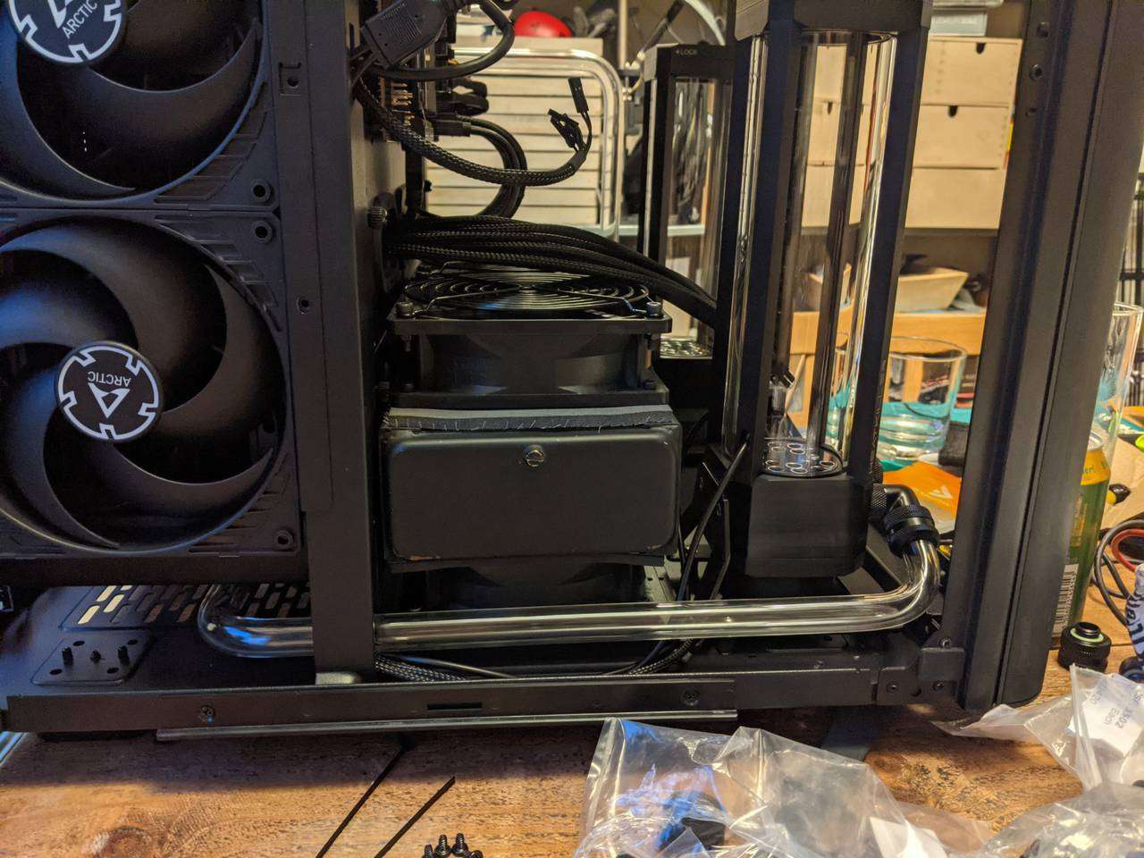
This was a bit difficult to gauge where to bend the tubing, but I used the 90° tube bending guide I have to approximate where the bends were needed and managed to get it right first time thankfully, as this section required just less than a full length of tubing.
The case has pass-through holes in the bulkhead that are just big enough to accomodate 16mm OD tubing. The pass-through hole is literally only just big enough however, so it meant that I couldn’t angle the tubing very much when feeding it through, and had to remove the rear radiator and bracket in order to get the tubing in place. That was pretty annoying as the radiator mounts to the bracket via the (short) screws for the fan which have to be screwed in “blind” with an allen key (I couldn’t find any black #6-32 screws with a suitable length to pass through the whole fan, bracket, and neoprene gasket, through to the radiator).
The radiator end of the tubing passes under the radiator and into a compression fitting connected to two 90° adaptors that provide that 180° turn back into the radiator port.
GPU loop drain
The section of tubing from the T-junction, near the radiator outlet, running to the GPU loop drain was a bit tricky as it required a 180° bend followed immediately by a 90° bend. When you bend the tubing near an existing bend, the existing bend can quite easily start to relax and start to undo itself. Some very determined holding of the tubing when doing the 90° bend made it just possible to achieve a nice looking section.
The GPU loop is incomplete and will require two more sections of tubing. One from the radiator outlet to the GPU block inlet, and one from the GPU block outlet to the pump inlet. This will have to wait until I have the graphics card and GPU block installed to measure up where to bend and cut those sections.
Leak test of CPU loop
The CPU loop was complete at this point, so I found out which pins of the PSU can be bridged with a wire (or paper clip) to power it on without the motherboard connected, and connected just the CPU loop’s pump to the PSU. This allows you to easily control the pump with the PSU’s own on/off switch when filling with water.
I was pretty confident that the loop would not leak. Each compression fitting has four O-rings, and I made several checks of each fitting to ensure that they were as hand-tight as I could get them. I laid down some tissue paper to be able to easily see any leaks or drips and filled the loop with plain deionised water. I used deonised water to leak test the loop as I had two and a bit litres on hand and didn’t mind wasting it in case there were leaks.
I ran the leak test for over 24 hours. There were no leaks and the water level in the reservoir had settled after all the tiny air bubbles had eventually ended up at the top of the reservoir (after flying through the loop many times!)
With the leak test successful, I drained the deonised water and filled the system with distilled water and Mayhem XT-1 Nuke V2 (Clear) concentrated additive to prevent corrosion and algae.
Final thoughts
I was a bit apprehensive about doing the bending of the acrylic tubing as it’s not something I’ve done before. I did already have a heat gun, and had used it recently to install some roof flashing (wide silver surfaced tape with a black rubbery back that becomes sticky when heated) on the joins of a carport when replacing the roof panels. That’s a different job entirely but did mean I had at least become acquainted with the power tool that I would use to bend the acrylic tubing.
It was a relief that the tubing I got was exactly 16mm in diameter. I thought it might be slightly off due to tolerances, but it literally measured 16.00mm in my digital caliper! I definitely recommend Kitronik as an acrylic tubing source if you are in the UK based on this experience. The tubing (10 x 495mm lengths) was individually wrapped in film, inside bubble wrap, inside a hard and thick cardboard poster tube with strong plastic caps, fastened with industrial strength staples. So each piece was immaculate and free of scratches, dust and chips.
I didn’t mention before, but I used a ~12mm diameter silicone rod (it looks like a floppy translucent cylinder, about 1m long) inside the tubing while bending. This prevents the tube from kinking or deforming when the bend is applied. For the first few sections, I just pushed the rod in dry (haha), but after putting a couple bends in the tubing, the friction on the walls around the bends makes it really hard to pull the rod out. When this happened, I had to drip some water in the tubing (after it had cooled sufficiently in the air, which took ages, to prevent sudden cooling from shattering the tubing) and add some drops of dish washing liquid detergent to reduce the surface tension. This let the silicone rod slip out very easily. After doing this once, I just pre-wet the silicone and spread a drop or two of the liquid detergent on it so that it would be possible to retrieve after doing multiple bends. This had an added benefit of providing a bit of an early visual hint of when the tubing was coming up to temperature, as the tiny bit of water in the tube would start bubbling as it “came to the boil”. The downside to this is that it made me think I’d overcooked the plastic (causing the bubbles inside the plastic itself) every time the water boiled!
Anyway, that’s it for (most of) the tubing. I’ll have another update (in Part 2) after the graphics card and GPU block have arrived when I do those last couple sections of tubing.
With the tubing done, I could attend to all the cables and tame them with some gentle cable management. It’s one of the final stages of completing this build, so stay tuned for that!
Product Links
You can support this website by purchasing items via the following Amazon Associate links.
- Tools
- Watercooling fittings
- Barrow G1/4 Male Rotary to 90 Degree Female Angle
- Barrow G1/4 Male Rotary to 45 Degree Female Angle
- Barrow G1/4” 3-Way Ball Fitting
- Barrow G1/4 Hex Blank Plug
- Barrow G1/4 Male Rotary to 90 Degree Female Angle (4 Pack)
- Barrow G1/4 Male Rotary - G1/4 Female 4 Way T-Splitter
- Barrow G1/4” Fillport Fitting
- Barrow G1/4” Mini Valve with ABS Handle
- Barrow G1/4” to 16mm Hard Tubing Compression Fitting, 4-Pack
- Radiator