


The Thermaltake Level 20 HT case is designed to support two separate water cooling loops, with some bulkhead holes that can accomodate up to 16mm OD tubing, as well as mounting platforms for the Thermaltake pump-reservoir towers. I don’t like the look of the Thermaltake pump-reservoirs, and I already had two Laing D5 pumps, so I got the Watercool Heatkiller Tube 200 D5 reservoirs. This meant I needed to drill some extra holes in the case’s base to fit the mounting brackets for the pump-reservoirs. I also wanted to use some G1/4” pass-through fittings in the bulkhead to make the CPU tubing neat and easily removeable when removing the CPU block as well as two pass-through fittings in the rear section’s base to use as drain ports.
Test fitting and marking out
Pump-reservoir brackets
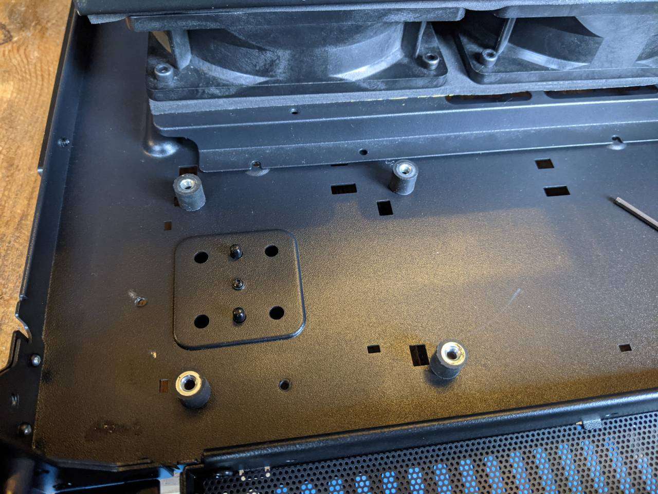
I started out by placing the pump-reservoirs roughly where I wanted them to be, and then shuffled the brackets around a bit to see if I could use any of the existing rectangular holes (that are there to provide tab slots for the Thermaltake-compatible reservoir platforms).
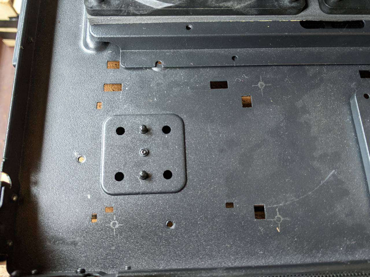
One of the large rectangular holes is in a suitable position for the Watercool Heatkiller Tube 200 D5 bracket, so I marked out the remaining three holes in pencil.
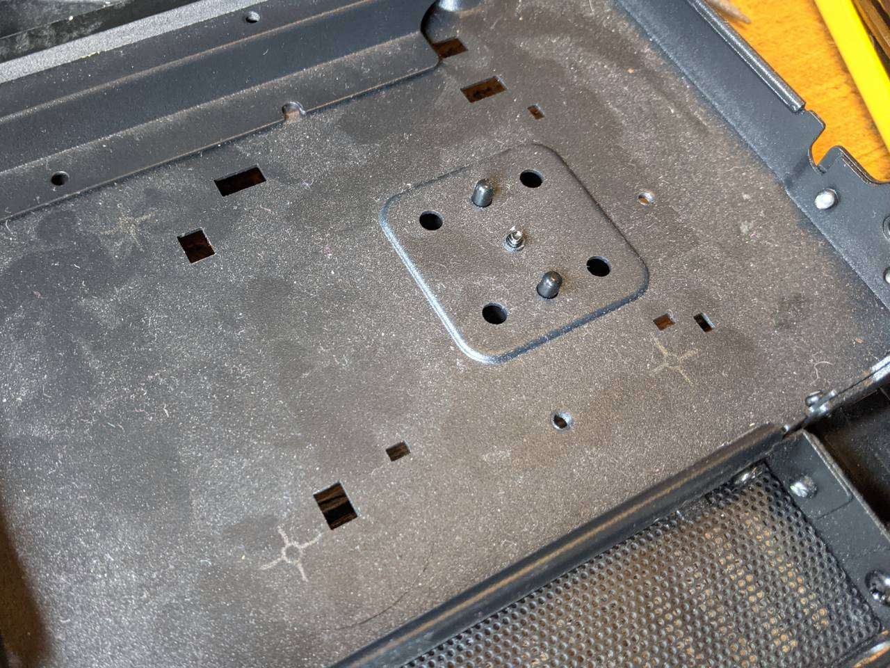
The same set of three holes was needed on the other side for the other pump-reservoir.
Bulkhead pass-through for CPU loop
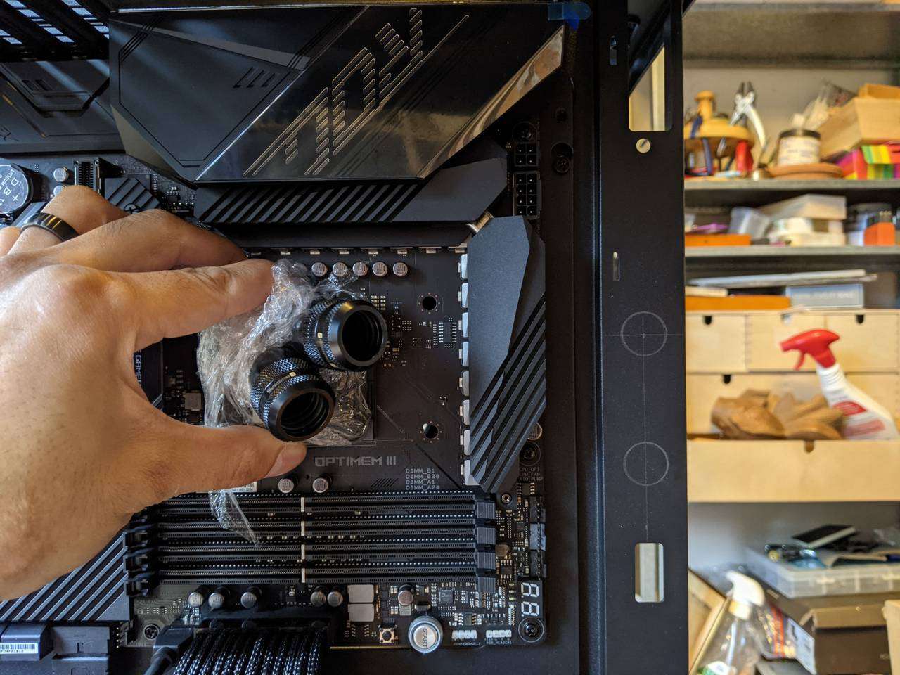
I held the D-Tek FuZion V1 CPU block roughly in position to get an idea of where the bulkhead pass-through fitting holes would be, and marked those out in pencil too.
Seeing if GPU pass-through holes required
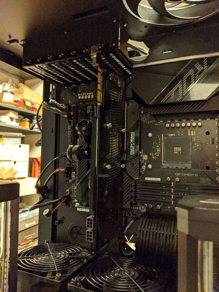
As I don’t yet have a modern graphics card for this build (but finally have managed to order one!) I used an old GTX260 with Swiftech MCW60 GPU-only block to get an idea of where my graphics card ports might end up.
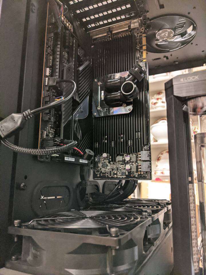
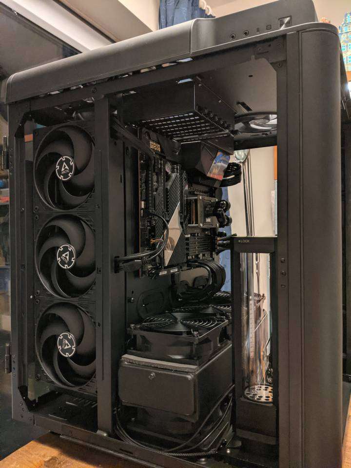
Using a thin scrap of neoprene foam as a make-shift bendable measuring device (that wouldn’t scratch up the case like a tape measure), I decided that the tubing to the graphics card’s block inlet could use the rubber-grommeted pass-through hole (pictured below the motherboard and just above the CPU radiator-fan stack), and the block outlet could just run down to the pump inlet. So there was no need for G1/4” pass-through fittings for the GPU loop.
Masking out the drilling positions
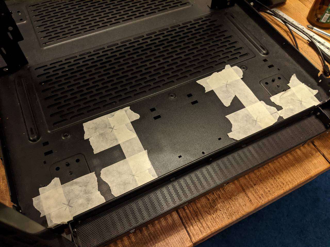
As standard good practice for drilling holes, I used some masking tape for the marked out hole positions to protect the paint work from slipping drill bits.
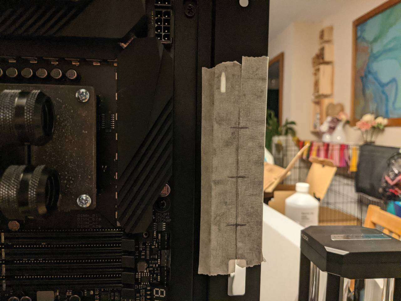
The same masked-marking was done for the bulkhead pass-through fitting holes.
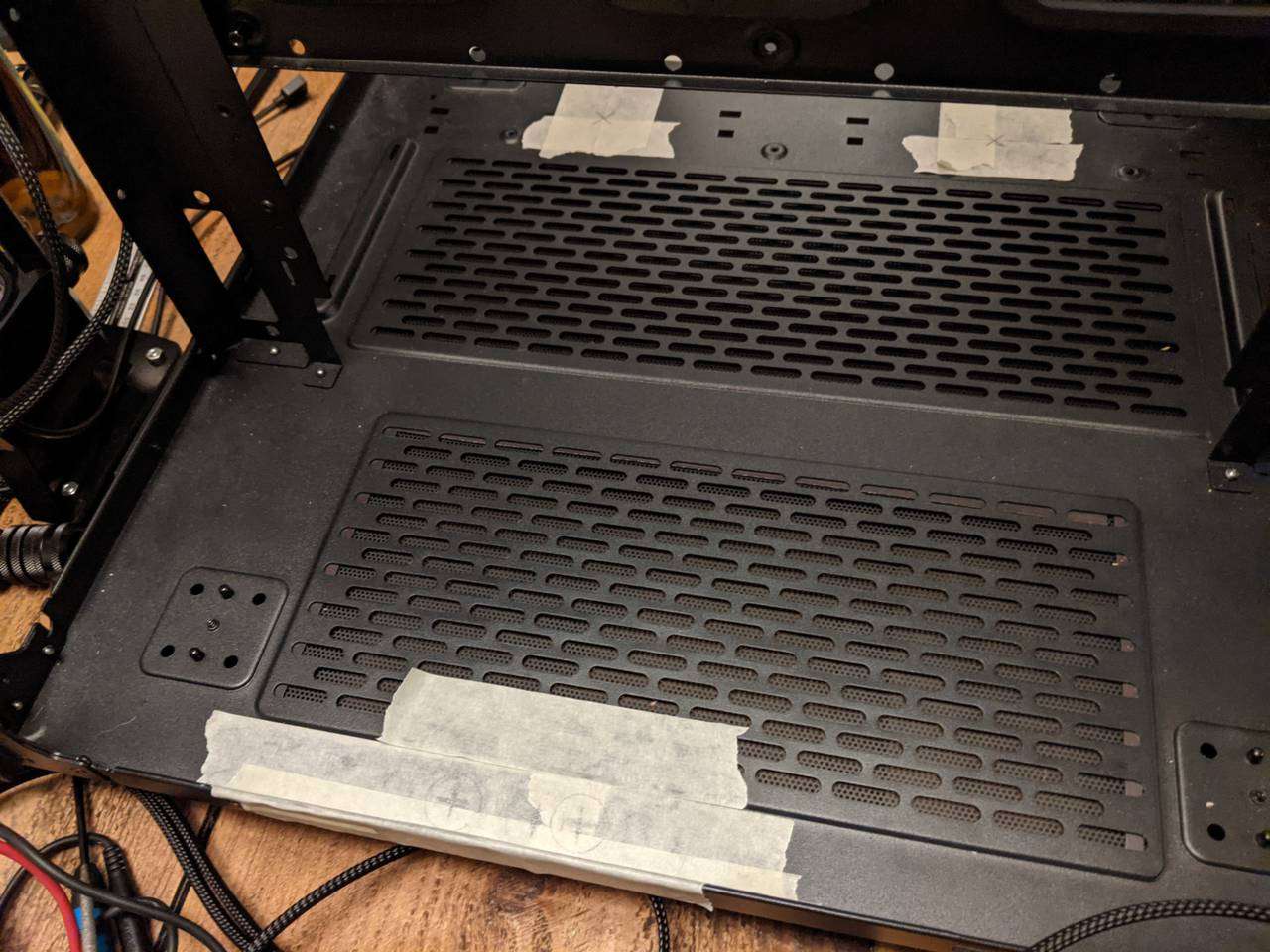
Round at the back of the case, I marked out pass-through hole positions for drain ports for each loop. These positions will allow the loops to have T-sections that can curve around to accomodate a stop valve.
Cut and filed
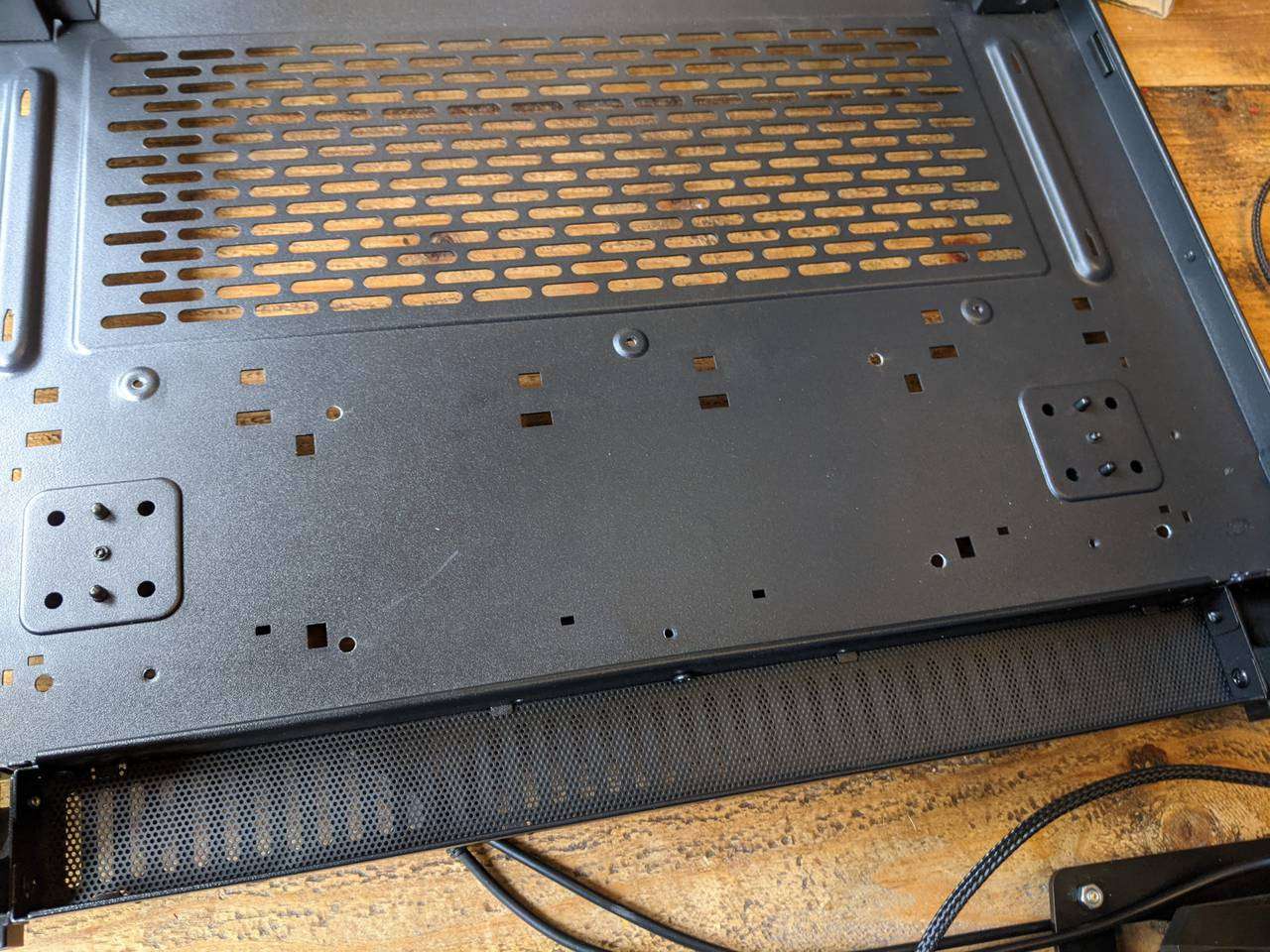
With the holes for the reservoir brackets drilled, I used a round needle file to deburr them.
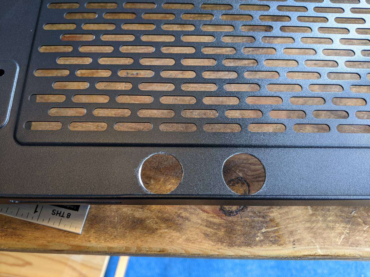
Similarly, for the drain port holes cut with a holesaw, a half-moon needle file deburred the sharp edges.
If you look closely, you can see that the distance between the bulkhead holes isn’t exactly equal, but the threads of the fittings sit loosely enough in the holes that it should be possible to shuffle them up/down to make them appear more equidistant.
Mounting and installing
These vibration isolation feet are rubber with a threaded hole on top and a machine screw protuding from the bottom. The screw underneath secures with a washer and nut.
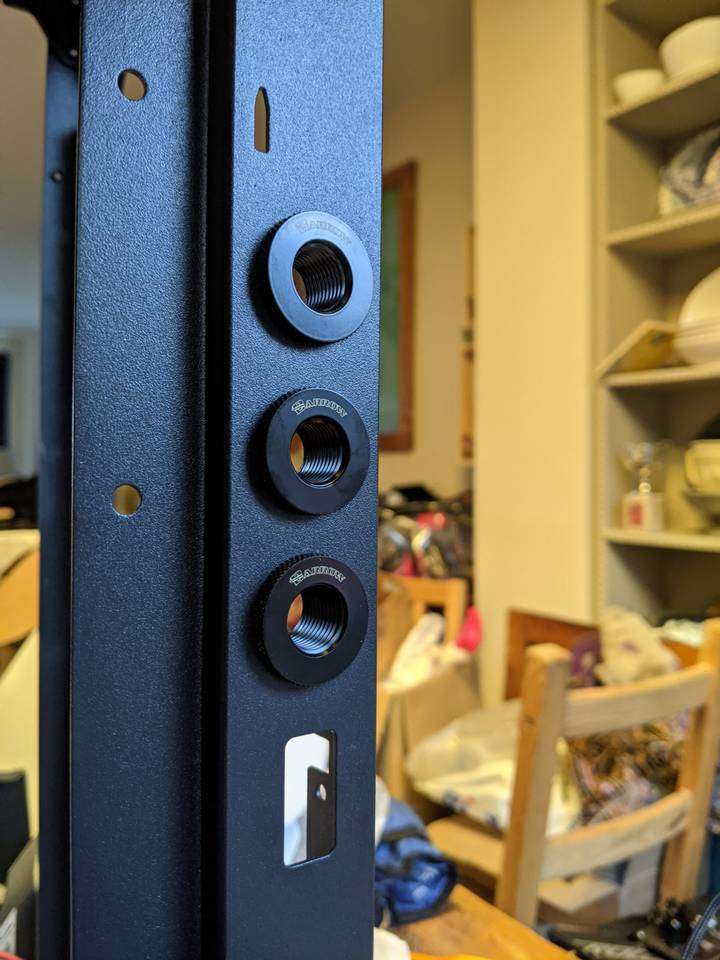
I used Barrow fittings throughout and these G1/4” pass-through fittings had plenty of room in this section of the bulkhead section that separates the front and rear chambers.
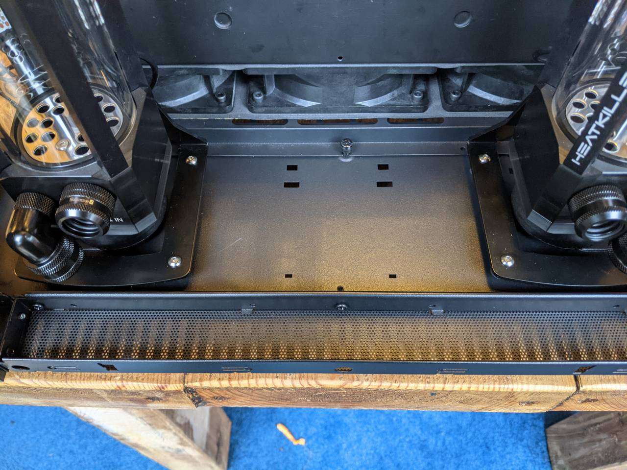
The reservoir brackets have hex head screws that attach through to the isolation feet.
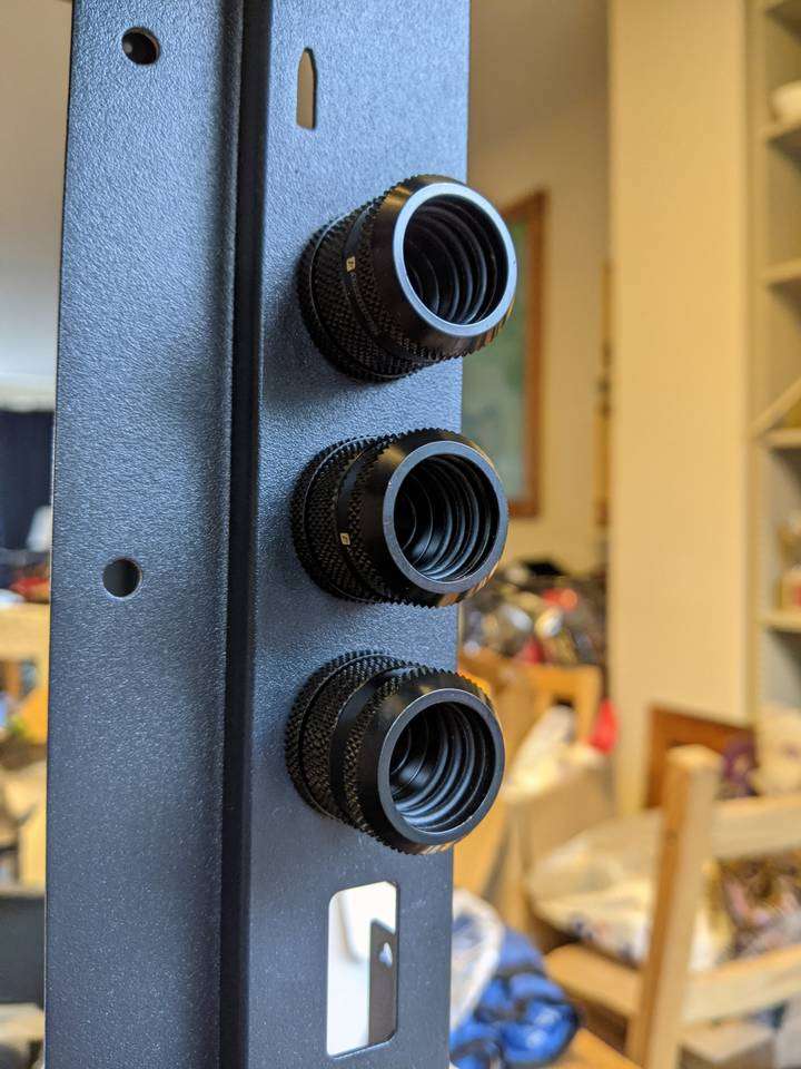
These Barrow fittings will ensure a secure fit for the CPU loop tubing. Each fitting has three O-rings internally in addition to a fourth O-ring that is installed on the tubing.
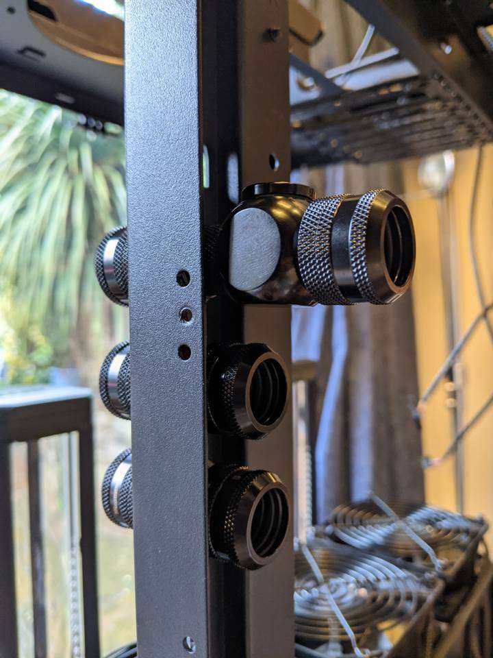
I used a T-junction fitting at the rear of the top pass-through fitting, with a stopper cap on one of the holes to provide an air bleed port for draining/filling. This will be the highest point of the entire CPU loop.
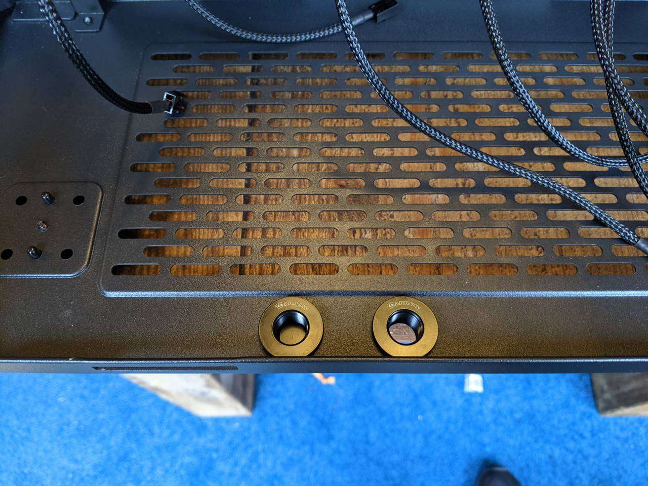
The pass-through fittings on the base were fitted, ready to have 90° fittings, stop valves, and stopper caps attached.
You can see that the resulting valved drain ports at the base of the rear chamber resemble water taps/faucets.
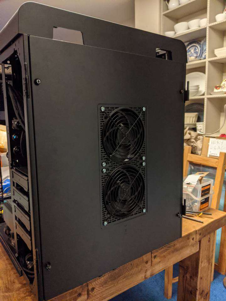
Improving the rear chamber airflow
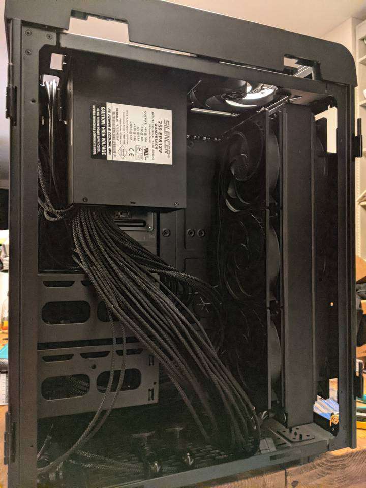
In the last picture you can see that the rear chamber has a fan at the top pulling air up. This blows up to the top glass panel and out of vents towards the side of the top. It looks somewhat restrictive, but there is also the option to mount 120 or 140mm fans to the rear panel.
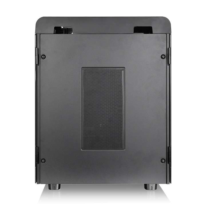
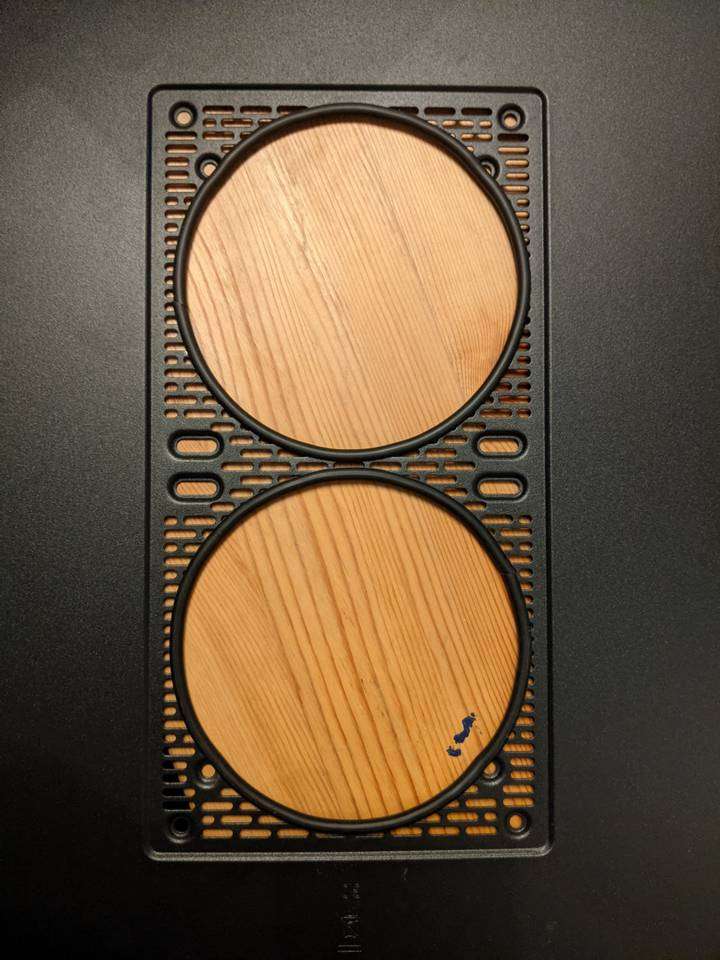
The rear panel has a slotted area to allow airflow to/from mounted fans as well as a rectangular shaped mesh with fine holes that attaches with magnetic strips. This mesh is intended as a dust filter but as I want the heat in the rear chamber to be exhausted from the back it doesn’t make any sense to use the mesh filter. The slotted section of the panel looks quite restrictive too, so I wanted to remove it to stop it impeding the airflow from the fans.
A big hole needs a big holesaw
You can cut steel panels with various power tools including a jigsaw and rotary tool with cutting discs, but for nice circular holes I prefer to use a holesaw. For the Arctic P14 PWM (140mm) fans I’ll be mounting to the rear panel, the most suitable size of holesaw is 127mm.
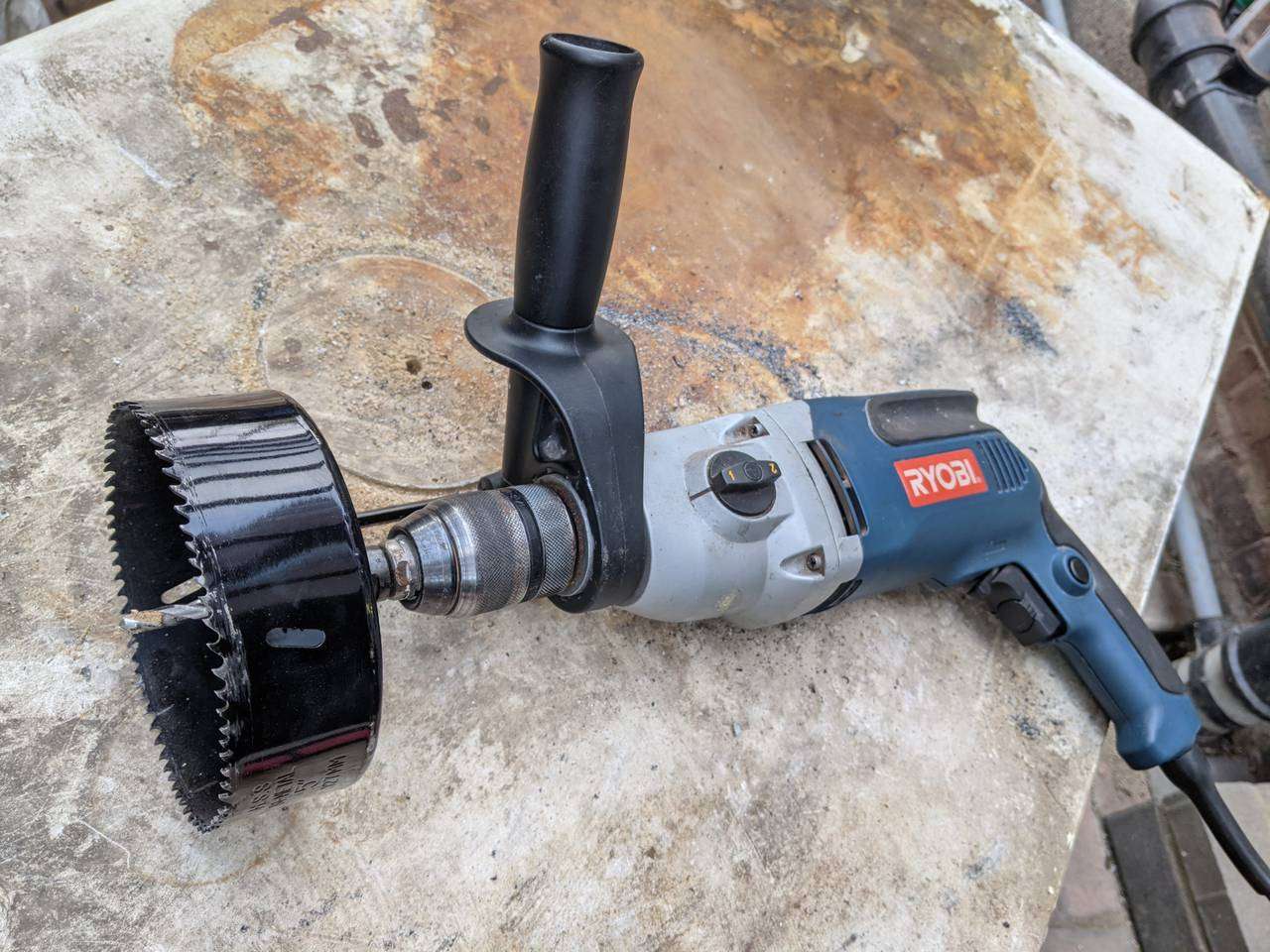
A big holesaw cutting through steel needs a powerful drill. My 1050W Ryobi drill in 1st gear has so much torque that when a holesaw catches on the workpiece the drill will almost rip your hand off or turn your entire body around the drill axis!
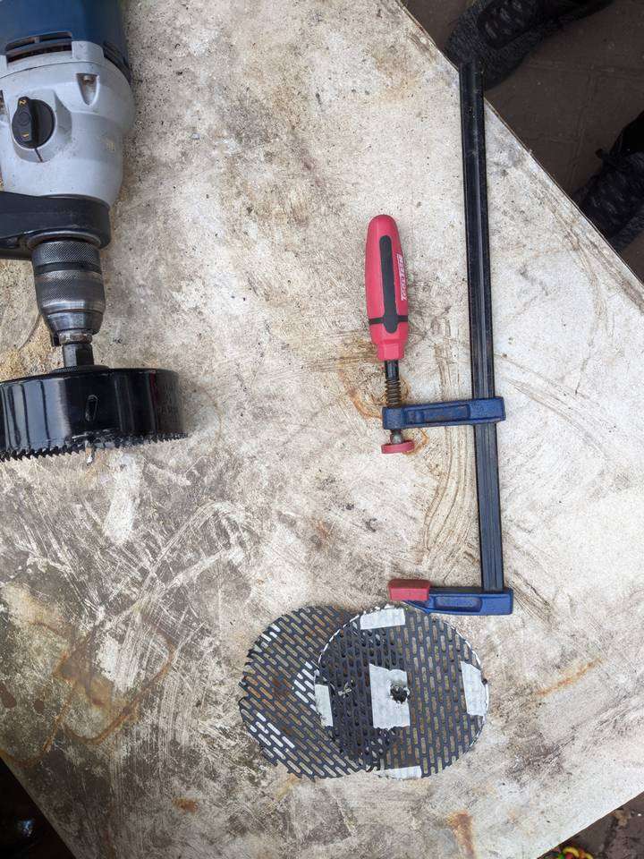
I used an old kitchen worktop as a bench, and some scrap wood and clamps to secure the panel while cutting, and provide a statically positioned hole for the drill bit in the holesaw arbor to keep the holesaw cutting position from drifting.
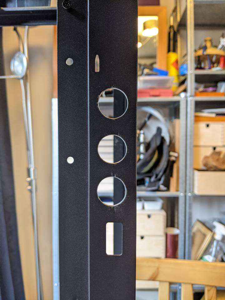
Big holes cut
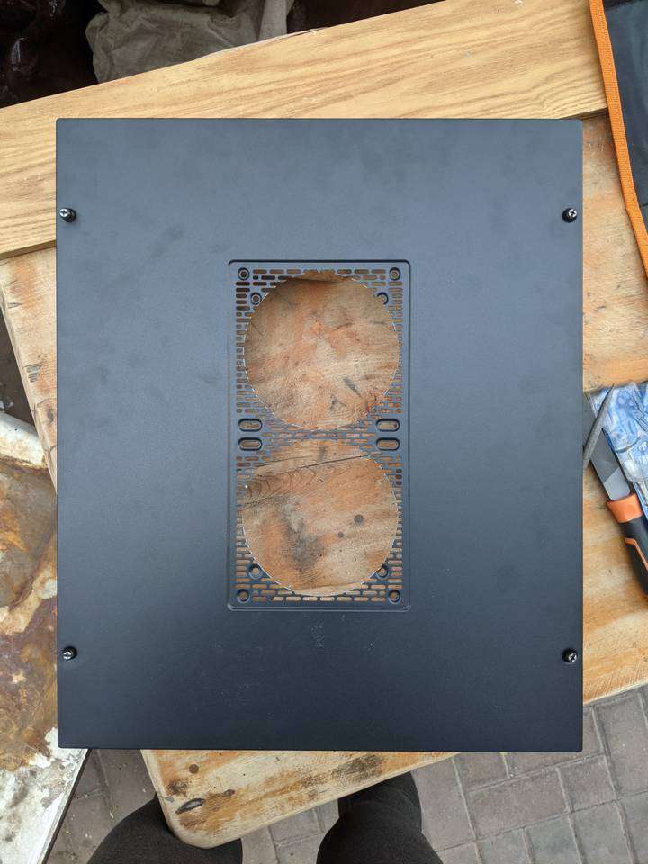
It was incredibly difficult to holesaw cut through this slotted panel as the holesaw teeth often caught on the slots. Each time this happened the drill jolted in my hand and smashed my left thumb knuckle no matter how firm I held the drill. However, the resulting holes after finishing the holesaw cutting looked almost perfectly aligned, definitely acceptable, and I didn’t scratch up the paintwork.
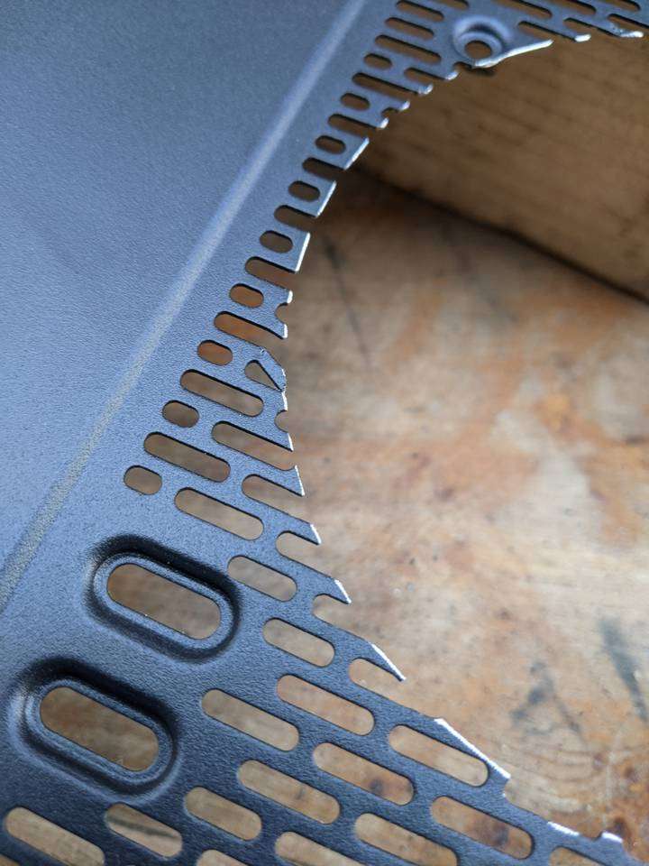
Some of the slotted sections became bent from the holesaw catching on them, but it looked like I could just bend them back with sniped-nose pliers and file off the protuding excess.
Hole edges neatened with edging strip
After sorting out the bent bits and doing some deburring file work, I used some silicone rubber edging strip to line the edges, cut at an angle on the ends for a glue-free press fit.
Rear panel modded fan holes result
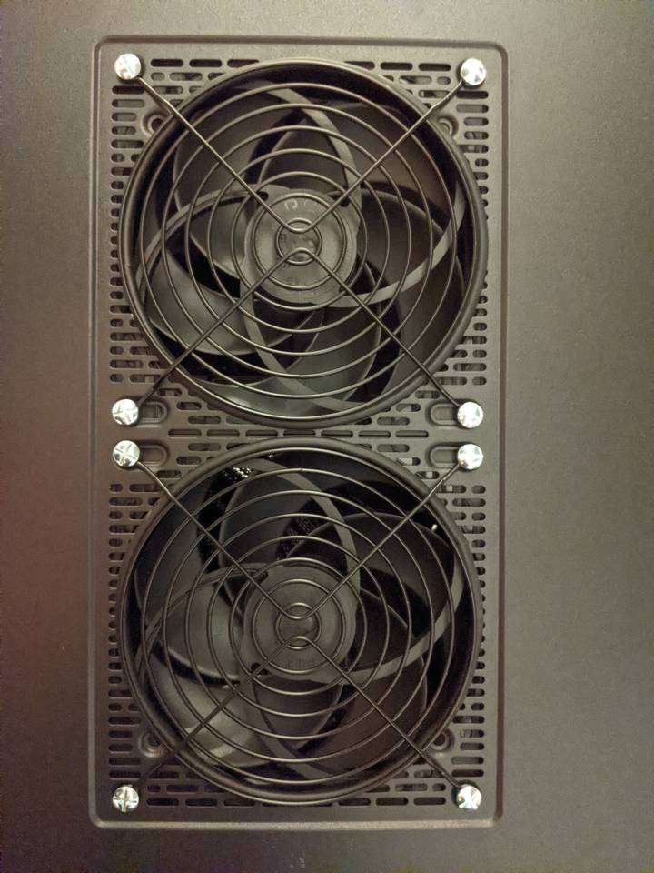
I had run out of suitable length black machine screws at this point, so I just used some plain steel ones. I did manage to find some black wire 140mm fan grills though.
The resulting look of the rear panel looks neat and respectable, and like it will allow the two fans to belt out plenty of warm air eminating from the 420mm radiator in the rear chamber.
Case modding complete
I’m going for an understated, matt black, industrial looking build, so these modifications are merely functional to allow better water cooling tube routing and better cooling performance via greater heat expulsion at the rear. With those done, I don’t have any further case mods planned, at least for the initial build.
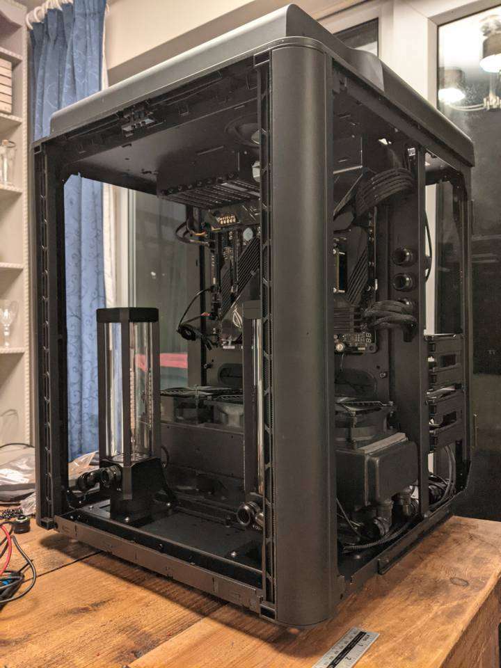
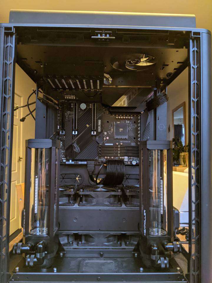
You’ll notice with most of the hardware installed, there is a fairly large void between the two reservoirs. The case comes supplied with a small platform to mount a 2.5” disk on the case floor. Some sort of snazzy RGB SSD is supposed to be on show here but, as I have no interest in RGB disks nor showing them off, I have some vague intentions to make some sort of bracket to mount an LCD display for hardware info like temps, voltages, frequencies, etc.
With all the water cooling hardware installed (apart from the not-yet-purchased GPU block), the build was in a state where I could move on to tackling the hard-line tubing to connect the water cooling components.
So that’s up next! Stayed tuned, stay cool…
Product Links
You can support this website by purchasing items via the following Amazon Associate links.
- PC case
- PC case fans
- PC case fan grills
- Holesaws
- Holesaw arbors